CFD Modeling Using ANSYS ICEM CFD & ANSYS CFX
This mini project /assignment deals with the geometry creation for 2D missile geometry. This mini project tests your understanding of various geometry creation options available in ANSYS ICEMCFD. After completing this mini project you will be comfortable in geometry creation/repair operations for simple geometries.
Prerequisites
The main pre-requisite for this assignment is basic understanding of geometry creation available in ANSYS ICEMCFD. Before taking this assignment, please make sure that you have gone through necessary lessons. The functionalities you need to use to complete this test are well explained in lessons “Geometry creation in ANSYS ICEMCFD”.
Problem Definition
Missile geometry given in this problem is typical missile geometry used in aerospace industry. The objective of this assignment is to create the missile geometry in 2D using ANSYS ICEMCFD. The geometry is to be generated to carryout external flow CFD simulation. All geometry dimensions are given in Figure 1. As shown in the Figure 2, a CFD domain needs to be created around the missile geometry for external flow simulation. You need to decide what extent of CFD domain should be considering the external flow requirements.
Figure 1: Geometry details (Note: All dimensions are in mm.)

Figure 2: External domain
Once the missile and external domain geometry is created, you need to create following parts to assign boundary conditions:
- Inlet
- Outlet
- Tunnel walls
- Missile walls
Download Input Files:
This mini project does not require any input files. Use geometry dimensions given above to create the geometry. You can download the PDF copy with details of this mini project from link below. Its compressed zip files, so download and unzip the file to get PDF copy.
You can also download PDF instruction file from “Shared Files” section on lesson page.
Results and Discussion:
If you have any specific query about the mini project or want to share the results of this project, please post them on course discussion forum.
This mini project deals with the multiblock mesh generation for 2D missile geometry. This mini project tests your understanding of various multiblock mesh generation options in ANSYS ICEMCFD. After completing this mini project you will be comfortable in creating multiblock structured meshing for simple geometries.
Prerequisites
The main pre-requisite for this test is basic understanding of multiblock hexahedral meshing using ANSYS ICEMCFD. Before taking this test, please make sure that you have gone through lessons on “Structured Hexahedral meshing”.
Problem Definition
This is an extension of previous mini project “Geometry creation for 2D missile geometry”. Missile geometry given in this problem is typical missile geometry used in aerospace industry. The objective of this assignment is to generate a 2D multiblock structured mesh. The mesh is to be generated to carryout external flow CFD simulation. All geometry dimensions are given in Figure 1. You can create the new geometry using given dimensions or use the geometry created in “Geometry creation for 2D missile geometry” mini project. We have also given the geometry as input if you want to start with readymade geometry.

Figure 1: Geometry details (Note: All dimensions are in mm.)
If you wish to create geometry before starting this mini project, make sure that you create domain necessary for external flow analysis as shown in Figure 2. You need to decide what extent of CFD domain should be considering the external flow requirements.

Figure 2: External domain
Once the missile and external domain geometry is created, you need to create following parts to assign boundary conditions:
- Inlet
- Outlet
- Tunnel walls
- Missile walls
Hints
- You can assume the turbulence model that would be used for simulation is in k-ε with standard wall functions. This turbulence model demands Y+ in the range of 30 to 150. You can use this data to calculate the first cell height. This is just given as a procedure to be followed. You can apply the same procedure for correct turbulence model for external flow over missile.
- Spend more time on deciding the block topology. Sketch the block topology on a paper roughly before you start creating block topology in ANSYS ICEMCFD.
Download Input Files
Links to download all necessary inputs files are given below. They are compressed zip files. Download them in one folder and unzip the files. This would create all necessary inputs files along with PDF copy of this project details. The geometry files is given in ANSYS ICEMCFD format (tin). This file is created using ANSYS ICEMCFD 13.0 version and would not work with any lower version.
You can also download both the files from “Shared Files” section on lesson page.
Results and Discussion
If you have any specific query about the mini project or want to share the results of this project, please post them on course discussion forum.
This mini project deals with meshing of tube in tube heat exchanger geometry. Multiblock hexahedral mesh needs to be created for complete geometry. After completing this mini project you will be comfortable in multiblock structured meshing for simple geometries. It is also expected that you calculate fist cell height using boundary condition material properties information given and create a mesh satisfying first cell height.
Prerequisites
The main pre-requisite for this project is basic understanding of multi-block hexahedral meshing using ANSYS ICEMCFD. Before taking working on this project, make sure that you have gone through our lessons on “Structured Hexahedral meshing”.
Problem Definition
In this project, a typical tube-in-tube heat exchanger geometry is to be meshed. The objective of this project is to apply your understanding of multiblock structured mesh on sample heat exchanger geometry. The geometry considered is just an extract of real life tube-in-tube heat exchanger. In reality, there would be large number of tubes and baffles.
The geometry considered for this project is shown in Figure 1.
Figure 1: Tube-in-tube heat exchanger geometry
It is also expected that you should create boundary layer mesh with appropriate Y+ values. You can assume k-ε turbulence model with standard wall functions for simulation. This turbulence model demands Y+ in the range of 30 to 150. You can use data given in Table 1 and Table 2 for designing your mesh.
|
|
Cold Water |
Oil Inlet |
|
Mass flow rate (kg/s) |
0.5 |
2 |
|
Temperature (°C) |
45 |
80 |
Table 1: Inlet conditions
|
|
Cold Water |
Oil Inlet |
|
Density (kg/m3) |
990 |
852 |
|
Conductivity (W/m°C) |
0.637 |
0.138 |
|
Prandtl number |
3.91 |
490 |
|
Kinematic viscosity (m2/s) |
0.602 x 10⁻⁶ |
37.5 x 10⁻⁶ |
Table 2: Material properties
In this project you have to create hexahedral mesh for the given tube-in-tube heat exchanger geometry using multi-block method in ANSYS ICEM CFD.
- There should be conformal mesh between two domain with domain labels water and oil. These three volume meshes will be used to provide appropriate volume conditions (material properties) in ANSYS FLUENT.
- The surfaces between two domains should have appropriate labels and they should be visible in ANSYS FLUENT. (This requires understanding of multi domain mesh using ANSYS ICEM-CFD).
- Quality of mesh: The minimum quality of mesh to pass this test is given below. If you can achieve the mesh quality more than criteria provided blow would be considered in grading scheme.
|
SR. No. |
Quality Criteria |
Minimum Value Expected |
|
1 |
3x3 Determinant |
0.3 |
|
2 |
Angle |
23 |
Table 3: Mesh quality
Hints
- You can assume the turbulence model that would be used for simulation is in k-ε with standard wall functions. This turbulence model demands Y+ in the range of 30 to 150. You can use this data to calculate the first cell height.
- In case of multi-domain mesh, the face between two blocks of respective volume domain will be projected on closest surface by default. This projection will carry the label of the surface on which it is projected.
- Spend more time on deciding the block topology. Sketch the block topology in a paper roughly for two or more cut/cross section of geometry
- Use scan plane to understand the issues in the volume mesh. This will help in improving the quality of mesh
Download Input Files
Links to download all necessary inputs files are given below. They are compressed zip files. Download them in one folder and unzip the files. This would create all necessary inputs files along with PDF copy of this project details. The geometry files is given in ANSYS ICEMCFD format (tin). This file is created using ANSYS ICEMCFD 13.0 version and would not work with any lower version.
You can also download both the files from “Shared Files” section on lesson page.
Results and Discussion
If you have any specific query about the mini project or want to share the results of this project, please post them on course discussion forum.
This mini project deals with meshing of catalytic convertor geometry. Unstructured tetrahedral mesh needs to be created for complete geometry. It is also expected that you create prism layer for capturing boundary layer physics. As this problem demands for modelling porous zone, your understanding of multi zone meshing is also tested. After completing this mini project you will be comfortable in unstructured meshing for simple geometries including multi domain problems.
Prerequisites
The main pre-requisite for this mini project is basic understanding of unstructured meshing using ANSYS ICEMCFD. Before taking this test, please make sure that you have gone through our lectures on unstructured surface, volume and prism meshing.
Problem Definition
Domain
Automobile -> Emission Control System -> Catalytic Converter
The flow field non-uniformities at the inlet of catalytic converters are considered undesirable for its performance. CFD simulations are widely used to study the flow distribution and the conversion efficiency of automotive catalytic converter. These studies help to understand the performance of the catalytic converter in order to optimize the converter design.
Device Understanding
Catalytic Converter is an important part of automobile’s emission control system. The job of the catalytic converter is to convert harmful pollutants (CO, NOx, and HC) into less harmful emissions before they leave the car's exhaust system.
Figure 1: Location of Catalytic Converter in Automotive
Image source: http://www.preciousmetals.umicore.com/recyclables/SAC/CatalyticConverter/
A catalyst is a substance that accelerates a chemical reaction, but is neither reactants nor products of the reaction. In the catalytic converter, there are two different types of catalyst at work, a reduction catalyst to reduce NOx emissions and an oxidation catalyst to convert unburned hydrocarbons and carbon monoxide to H2O and CO2 by oxidation. Both types consist of a ceramic / honeycomb structure coated with a metal catalyst, usually platinum, rhodium and/or palladium. The idea is to create a structure that exposes the maximum surface area of catalyst to the exhaust stream, while also minimizing the amount of catalyst required, as the materials are extremely expensive.
Figure 2: Catalytic Converter Working
Image source: http://www.preciousmetals.umicore.com/recyclables/SAC/CatalyticConverter/
Problem Definition
The catalytic converter under current study is shown in figure below. Nitrogen flows in through the inlet with a uniform velocity of 22.6 m/s, passes through two substrates which has square shaped channels and then exits through the outlet.
In order to reduce the cell count and complexity of problem, the substrates are modeled as porous media. In order to model the substrate as porous media, one need not to create the internal details of the substrate. The substrate will be modeled as single volume with porous media properties. Flow through substrate is characterized by viscous and inertial loss coefficients in flow direction. The substrate is impermeable in other directions.
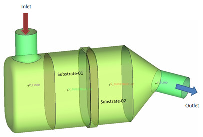
Figure 3: Catalytic Converter Geometry for Current Study
In this mini project you have to create unstructured mesh for the given catalytic converter using ANSYS ICEMCFD. The mesh requirement is as below:
- Appropriate mesh size should be calculated and used for meshing. The mesh size should be sufficient enough to capture the geometry features (curvature etc.) and to capture the flow features (boundary layer, turbulence etc.)
- There should be conformal mesh between all three domain with domain labels V_FLUID, V_Substrate-01, V_Substrate-02. These three volume meshes will be used to provide appropriate volume conditions (fluid/porous media) in ANSYS FLUENT.
- The surfaces between all three domains should have appropriate labels and they should be visible in ANSYS FLUENT. (This requires understanding of multi domain mesh using ANSYS ICEMCFD).
- Quality of mesh: The minimum quality of mesh to pass this test is given below. If you can achieve the mesh quality more than criteria provided blow would be great.
|
SR. No. |
Quality Criteria |
Minimum Value Expected |
|
1 |
3x3 Determinant |
0.3 |
|
2 |
Angle |
23 |
Hints
- You can assume the turbulence model that would be used for simulation is in k-ε with standard wall functions. This turbulence model demands Y+ in the range of 30 to 150. You can use this data to calculate the first cell height.
- Use scan plane to understand the issues in the volume mesh. This will help in improving the quality of mesh
Further Reading
- ANSYS FLUENT document on setting up porous media simulations
- ANSYS FLUENT tutorial named “Modeling Flow Through Porous Media”
- http://www.autocatalyst-recycling.umicore.com/catalyticConverter/
Solver Settings
Although carrying CFD simulation is not a part of this mini project, you can carry out CFD simulation to check the performance of mesh you have created. In this section, the necessary boundary conditions for solver setup using ANSYS FLUENT are given. You can use this boundary condition if you are willing to do the simulation on created mesh.
You can use following data for setting up simulation in ANSYS FLUENT:
- Dimension of geometry : mm
- Inlet gas : Nitrogen (N2) with velocity 22.6 m/s
- Outlet: Static pressure = 0 Pa (Gauge)
- Material properties of Nitrogen:
- Density: 1.138 kg/m3
- Viscosity : 1.663e-05 kg/ms
- Porous media properties:
|
Direction |
Viscous Resistance (1/m2) |
Inertial Resistance (1/m) |
|
Along Flow |
3.846e+07 |
20.414 |
|
Perpendicular to Flow |
3.846e+10 |
20414 |
Download Input Files
Links to download all necessary inputs files are given below. They are compressed zip files. Download them in one folder and unzip the files. This would create all necessary inputs files along with PDF copy of this project details. The geometry files is given in ANSYS ICEMCFD format (tin). This file is created using ANSYS ICEMCFD 13.0 version and would not work with any lower version.
You can also download both the files from “Shared Files” section on lesson page.
Results and Discussion
If you have any specific query about the mini project or want to share the results of this project, please post them on course discussion forum.
This mini project deals with the geometry creation for 3D missile geometry. This is an extension of previous mini project “Geometry creation for 2D missile geometry”. In this project, you are supposed to create 3D geometry and external domain for CFD analysis. This mini project tests your understanding of various geometry creation options available in ANSYS ICEMCFD. After completing this mini project you will be comfortable in geometry creation/repair operations for simple geometries.
Prerequisites
Before starting this project, it is expected that you have worked on previous project “Geometry creation for 2D missile geometry”. The main pre-requisite for this assignment is basic understanding of geometry creation available in ANSYS ICEMCFD. Before taking this assignment, please make sure that you have gone through necessary lessons. The functionalities you need to use to complete this test are well explained in lessons “Geometry creation in ANSYS ICEMCFD”.
Problem Definition
Missile geometry given in this problem is typical missile geometry used in aerospace industry. The objective of this assignment is to create 3D missile geometry using ANSYS ICEMCFD. The geometry is to be generated to carryout external flow CFD simulation. The end result of this project is shown in Figure 1.
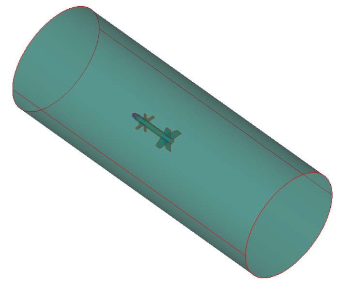
Figure 1: 3D CFD domain for external flow analysis
All geometry dimensions of missile are given in Figure 2. These dimensions are same as what are used in previous project “Geometry creation for 2D missile geometry”. So you can use that geometry file to start with. In case if you have not worked on previous project, 2D geometry file is provided as input for this project. (It is strongly recommended that you first work on 2D version of this project as that would give you good head-start for this project)
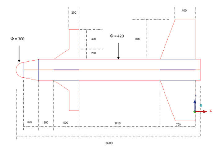
Figure 2: Geometry details (Note: All dimensions are in mm.)
There are four front fins and four back fins. All the fins has 5 mm thickness as shown in Figure 3.
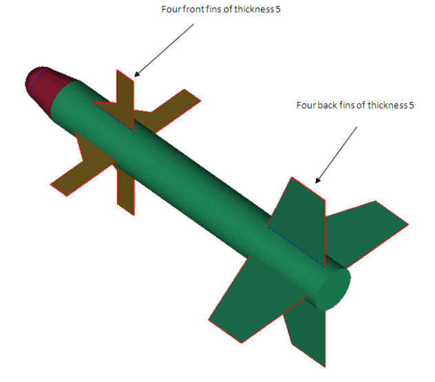
Figure 3: Fin thickness
CFD domain needs to be created around the missile geometry for external flow simulation. All the details of external domain size are shown in Figure 4.
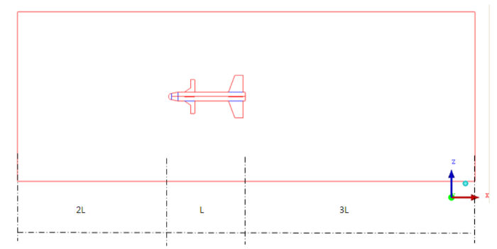
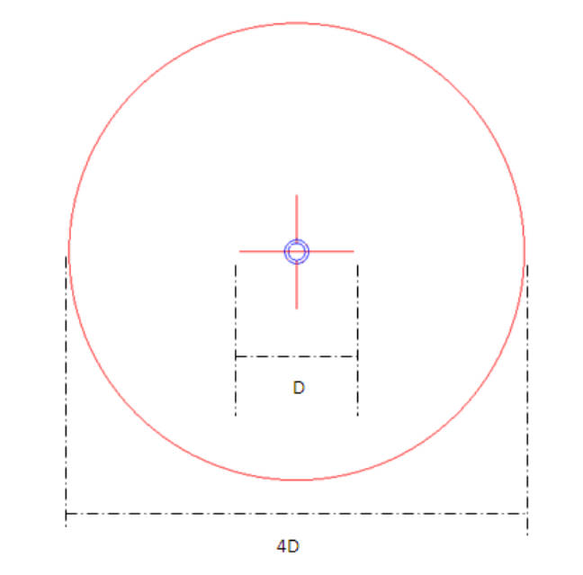
Figure 4: External domain dimensions
Once the missile and external domain geometry is created, you need to create following parts to assign boundary conditions:
- Inlet
- Outlet
- Tunnel walls
- Missile walls
- Front fins
- Back fins
Download Input Files:
This mini project does not require any input files as such. Use geometry dimensions given above to create the geometry. In case if you have not worked on 2D version of this project “Geometry creation for 2D missile geometry”, we have provided 2D missile geometry as input. You can download 2D version geometry as well as the PDF copy with details of this mini project from link below. Its compressed zip files, so download and unzip the file to get PDF copy.
You can also download PDF instruction file from “Shared Files” section on lesson page.
Results and Discussion:
If you have any specific query about the mini project or want to share the results of this project, please post them on course discussion forum.
This mini project deals with meshing of piping between two screw compressors outlet and oil separator inlet. Multiblock hexahedral mesh needs to be created for complete geometry. After completing this mini project you will be comfortable in multiblock structured meshing for simple geometries. The end goal of the project is not to generate mesh for any specific flow rates, but to create a blocking structure such that it could be used for any flow conditions later. The focus is on creating a blocking structure rather than create a mesh.
Prerequisites
The main pre-requisite for this project is basic understanding of multi-block hexahedral meshing using ANSYS ICEMCFD. Before taking working on this project, make sure that you have gone through our lessons on “Structured Hexahedral meshing”.
Problem Definition
The oil has a key function in a refrigeration system because it contributes to ensure lubrication of the mobile parts of the compressor, evacuation of the heat due to frictions of the mobile parts, and air tightness between the compression stages in rotating compressors.
All the oil does not stay in the compressor crankcase and a part is brought into the refrigeration system. This happens during start-up of the compressor, due to the sudden evaporation of the refrigerant dissolved in the oil, by the piston rings in piston compressors and by its close contact with the refrigerant in rotating compressors.
The volume of oil ejected by the compressor circulates with the refrigerant and has the following effects:
- Decrease in the oil level in the crankcase, which can lead to a mechanic breakdown
- Modification of the quality, physical and thermodynamic properties of the refrigerant
- Decrease in the efficiency of exchangers (evaporators and condensers); the loss of capacity can reach 30% with rabbet tube evaporators
- Oil retention in oil traps and low speed areas. This oil may return suddenly and generates a liquid hammer (slugging)
There are many techniques used for separating the oil form refrigerant. The current project details with a piping system connecting two compressor outlets to oil separator inlet. There are many objectives for which CFD analysis could be done. One of the CFD analysis objective could be to understand the flow dynamics inside the piping and at the inlet of oil separator. A uniform flow distribution at inlet could help us design and analyse oil separator. Another objective could be to check flow dynamics and its effect on oil droplets. This would help us understand how much oil is actually getting separated from refrigerant in the connecting pipe.
The focus of this mini project is to create a blocking structure suitable for piping geometry topology. Once the blocking structure is created, that could be adapted to any flow rate conditions later. It is also expected that you create required O-Grid blocking so that boundary layer mesh could be generated.
The geometry considered for this project is shown in Figure 1.
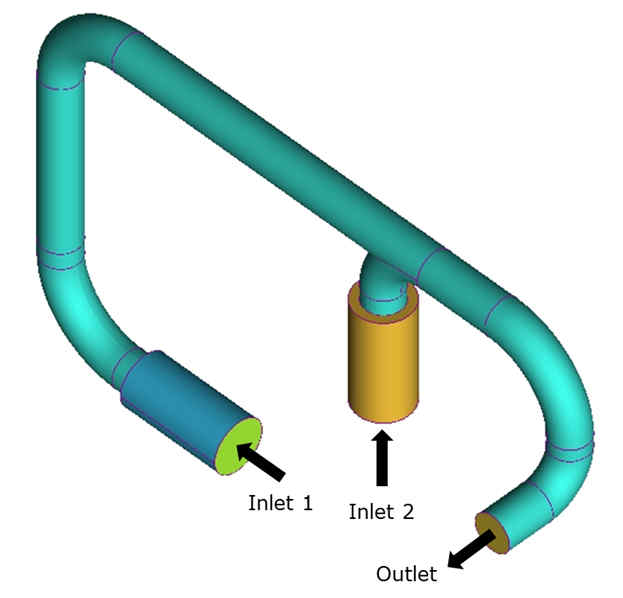
Figure 1: Screw compressor outlet pipe geometry
Sample Results
Below are few sample results provided for reference. Cross check you blocking structure and pre-mesh results with these results/images.
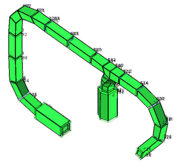
Figure 2: Blocking structure
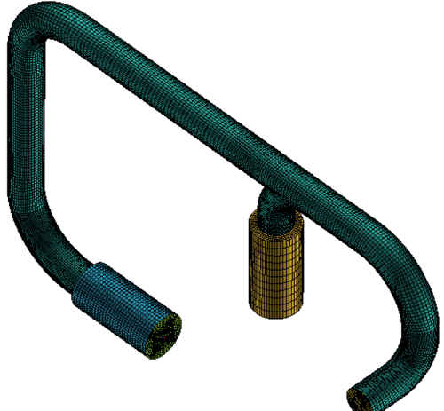
Figure 3 : Mesh
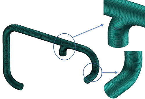
Figure 4: Mesh features
Hints
- Spend more time on deciding the block topology. Sketch the block topology in a paper roughly for two or more cut/cross section of geometry
- Use scan plane to understand the issues in the volume mesh. This will help in improving the quality of mesh
Download Input Files
Links to download all necessary inputs files are given below. They are compressed zip files. Download them in one folder and unzip the files. This would create all necessary inputs files along with PDF copy of this project details. The geometry files is given in ANSYS ICEMCFD format (tin). This file is created using ANSYS ICEMCFD 13.0 version and would not work with any lower version.
You can also download both the files from “Shared Files” section on lesson page.
Results and Discussion
If you have any specific query about the mini project or want to share the results of this project, please post them on course discussion forum.
This mini project about geometry cleanup and fluid domain extraction for computer cabinet with fan geometry. The geometry of empty computer cabinet with inlet grill is to be created. Complete fan geometry is provided as input which needs to be cleaned and assembled on cabinet. The objective of project is create assembly of cabinet and fan for flow analysis. The input fan geometry contains all components including solid parts. This geometry is to be cleaned for flow analysis.
Prerequisites
The main pre-requisite for this mini project is good understanding of various geometry operations available ANSYS ICEMCFD. It is also expected that you have understanding of what is fluid domain and what geometry details are required in case if only flow analysis is to be performed. Before taking this project, please make sure that you have gone through lesson on “Geometry Creation” and “Geometry cleanup for control valve tutorial”.
Geometry Cleanup – Why?
In an application engineer’s point of view, CFD is a three step process viz. pre-processing, solution and post-processing. The CFD process starts with defining the domain of interest within which governing equations are to be solve. Domain is defined by shape and size of all its confining boundaries. In almost all industrial cases the domain definition is created using CAD software and transferred to meshing software using neutral file formats like IGES, STEP etc.
Traditionally, the most time consuming part in complete CFD process is creating a good quality mesh. Considering the advancements in meshing techniques available in today’s meshing tools, lot of automation of meshing algorithm is done. The main bottleneck is making CAD geometry mesh ready or converting dirty CAD to clean mesh-able CAD.
All meshing algorithms needs a water tight geometry (defined within the constraints of the tolerance considered by meshing software). Creating a clean watertight geometry from dirty CAD is sometimes challenging and in most of the cases very time consuming job.
The geometry cleanup mainly depends on physics under consideration and computational power available for solution. If only flow analysis is to be done, the geometry of only “wet surfaces” should considered and all other components should be removed. In ideal situation, all geometry features should be captured in mesh. But that would result into huge cell count for most of the industrial problems. So the cleanup of small feature is required to be done to reduce the total cell count at the same time not to affect the flow physics considerably. Engineer should have good understanding of flow physics so that he/she can decide what sort of cleanup can be done.
In this project, the input CAD geometry of fan “RAW” CAD data. This CAD include many unwanted parts if only flow analysis is to be carried out. This CAD also contains many small features which should be removed.
Problem Definition
Objective
Axial fan is the device used where one needs large volume of fluid with moderate pressure rise. Axial fans have broad industrial and commercial users. They are used to introduce air or other gases into the process reactors for the chemical and pharmaceutical industries; to assist combustion in furnace; to dry agricultural and manufactured products; in air handling unis for cleanrooms used in pharmaceutical, biotechnology, hospital and micro-electronic industries; for roof and wall-mounted power ventilators; in commercial cooking exhaust fans; for dust collection and many more.
Prediction of flow field and performance of axial fan is an important aspect during design, modification and tubule-shooting. The commercial CFD tools are developed to predict accurate flow physics for such rotating components.
There are many standard axial fans available in the industry for different applications. In this mini project, axial fan used in Personal Computer (PC) for cooling purpose is considered. The purpose of this project is to clean provided RAW CAD data for flow analysis, to assemble the clean fan geometry with cabinet and to extract fluid domain for meshing.
Following are the steps to be completed in this project:
- Create empty cabinet geometry with inlet grill
- Clean RAW CAD data of fan
- Assemble the clean fan data with cabinet
The main objective is to extract clean fluid domain for flow analysis.
Geometry Details
Axial fan is the device used where one needs large volume of fluid with moderate pressure rise. Axial fans have broad industrial and commercial users. They are used to introduce air or other gases into the process reactors for the chemical and pharmaceutical industries; to assist combustion in furnace; to dry agricultural and manufactured products; in air handling unis for cleanrooms used in pharmaceutical, biotechnology, hospital and micro-electronic industries; for roof and wall-mounted power ventilators; in commercial cooking exhaust fans; for dust collection and many more.
The layout of geometry is shown in Figure 1.
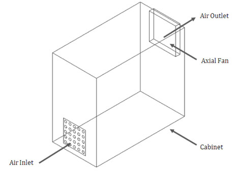
Figure 1: Geometry layout
Details of cabinet geometry are given in Figure 2
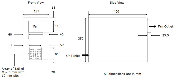
Figure 2: Cabinet geometry details
The grill is of size 85 x 85 mm located at the bottom. Fan is attached at top. The details of fan are given in Figure 3.
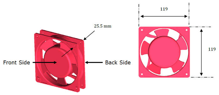
Figure 3: Fin thickness
Fan is required to be attached to cabinet such that the back side of fan is attached to cabinet and front side is towards the outlet.
Expected Tasks and Sequence
Following is the list of tasks involved in this project. They are listed in the sequence they should be carried out.
- Create the cabinet geometry with given dimensions
- Import fan geometry
- Move fan geometry to its correct location as shown in Figure 2
- Clean the fan geometry to have only wet surfaces required for flow analysis
- Remove small features of fan geometry to simplify geometry for meshing
- Create inlet grill
Download Input Files:
Links to download all necessary inputs files are given below. They are compressed zip files. Download them in one folder and unzip the files. This would create all necessary inputs files along with PDF copy of this project details. The geometry files is given in STEP format.
You can also download both the files from “Shared Files” section on lesson page.
Results and Discussion:
If you have any specific query about the mini project or want to share the results of this project, please post them on course discussion forum.
Working out the blocking strategy is the most critical step for creating structured mesh. It takes time for one to acquire required skills to generate blocking structure for complex geometry. It’s always a good idea to start with simple geometry topology and move towards complex topology. In this project, number of geometrical configurations are given in increasing complexity order. It starts with simple cylindrical geometry and the goes to more complex multi zone meshing. The end goal of the project is not to generate mesh for any specific flow rates, but to create a blocking structure such that it could be used for any flow conditions later. The focus is on creating a blocking structure and zones rather than create a mesh.
This mini project tests your understanding of various multiblock mesh generation options in ANSYS ICEMCFD. After completing this mini project you will be comfortable in creating multiblock structured meshing for simple geometries.
Prerequisites
The main pre-requisite for project is basic understanding of multiblock hexahedral meshing using ANSYS ICEMCFD. Before taking this project, please make sure that you have gone through lessons on “Structured Hexahedral meshing”.
Problem Definition
Project contains set of geometries. The focus of this project is to create a blocking structure suitable for all given geometries. Once the blocking structure is created, that could be adapted to any flow rate conditions later. It is also expected that you create required O-Grid blocking so that boundary layer mesh could be generated. It is advised that you should work on these geometries in the sequence they are given below.
For all geometries, two inputs are given, one the required dimensions to create the geometry and other the zone labels and type. It is expected that you create the geometry and make sure that your exported mesh (for any solver), would have the required zone labels and zone type.
For the geometries containing multiple zones, you have to create a mesh which is conformal at the zone boundaries. This requires connected blocking structure. The best way to create such blocking structure is to use “Top-to-Bottom” blocking approach. This requires one big block to be created first and then split and delete unwanted blocks to get required blocking structure
Single Cylinder
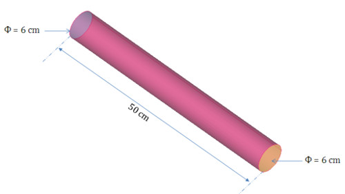
Figure 1: Dimensions
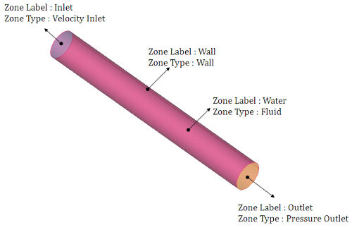
Figure 2: Zone assignment
Two Cylinders
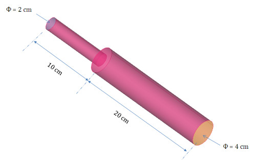
Figure 3: Dimensions
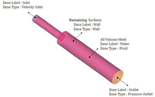
Figure 4: Zone assignment
Three Cylinders
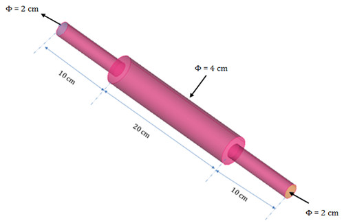
Figure 5: Dimensions
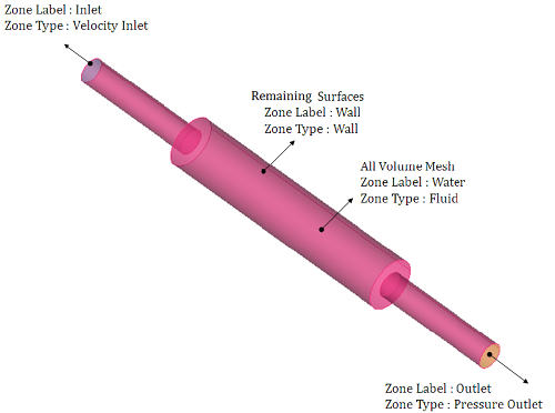
Figure 6: Zone assignment
Pipe with Thickness
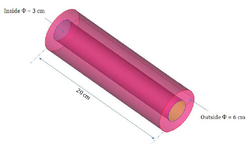
Figure 7: Dimensions
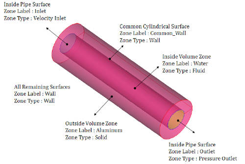
Figure 8: Zone assignment
Simple Shell-and-Tube
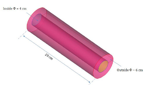
Figure 9: Dimensions
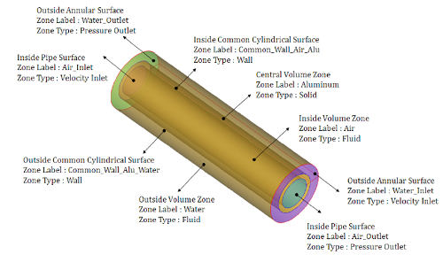
Figure 10: Zone assignment
Shell and Tube with Thickness
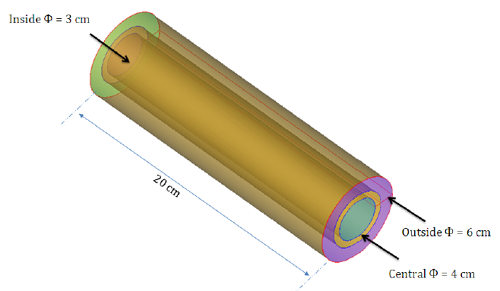
Figure 11: Dimension
Figure 12: Zone assignment
Pump a Like (2D)
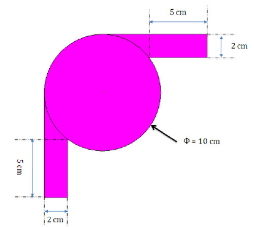
Figure 13: Dimensions
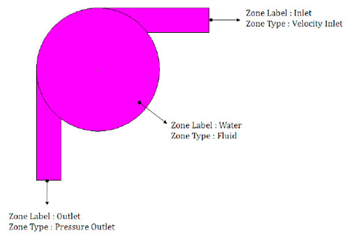
Figure 14: Zone assignment
Sector with Rotational Periodicity
Following different activities are expected for this geometry:
- Only sector mesh: Create a sector blocking and mesh with periodic boundary conditions.
- Complete mesh (approach 1): Create a sector blocking and rotate blocking along with geometry. Create mesh for complete geometry.
- Complete mesh (approach 2): Create sector blocking and sector mesh. Load the sector mesh and rotate (with merging nodes) to get complete mesh.
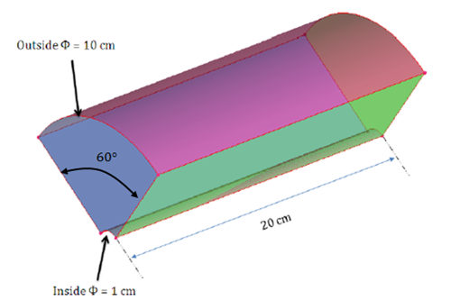
Figure 15: Dimension
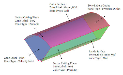
Figure 16: Zone assignment
Download Input Files
This mini project does not require any input files. Use geometry dimensions given above to create the geometry. You can download the PDF copy with details of this mini project from below link. Its compressed zip files, so download and unzip the file to get PDF copy.
You can also download both the files from “Shared Files” section on lesson page.
Results and Discussion
If you have any specific query about the mini project or want to share the results of this project, please post them on course discussion forum.
“Meshing is an art”. It’s not only about knowing the tools and techniques available in software but also about applying those tools at right time and for right purpose. Understanding the tools, how it work etc. is required, but practicing those tools on various geometries is must for developing mesh expertise.
Here we have given set of clean geometries of only fluid domain which you can practice on. All of the geometries are extract of real life industrial problem. These geometries are ranging from simple to moderately complex configuration.
Prerequisites
The main pre-requisite for this project is good understanding of all meshing tools and techniques available in ANSYS ICEMCFD. It is expected that you have gone through the lessons on Unstructured and multi-block structured meshing before you start working on these geometries. It is also advised that you go through tutorials, demos and complete all mini projects before you start working on these geometries. It is strongly advised not to start working on these geometries before you complete all lessons, demos, tutorials and mini project.
Problem Definition
All the geometries given are extract of real life industrial problems. There two ways one can mesh these geometries. First, you can do unstructured meshing with triangular, tetrahedral and prism cells. Second, you can create all quadrilateral and hexahedral cells using structured multi-block meshing technique.
It is expected that you mesh all the geometries using both unstructured and structured meshing approaches. This will help you practice and perfect both meshing techniques. When you start working on any real life project, you may choose one of the meshing technique depending on the complexity of geometry, time available for meshing and overall accuracy requirement.
The main idea is to create a representative mesh for all the geometries. The mesh size always depends on the flow physics you want to capture. The inputs for flow conditions are not given here. You can assume any flow condition for calculating the mesh size. May be you can do some literature survey to find a similar device or configuration and extract the flow conditions and use those conditions to calculate the mesh size. As mentioned, idea is to learn how to mesh these geometries rather than crating a mesh for specific flow condition.
It is expected that you create appropriate boundary layer mesh. In case of unstructured mesh, put prism layers with at least 4 layers. In case of structured meshing, create appropriate bunching of nodes near wall.
Problem Definition
A brief description of geometry and link to download geometry file is given below. All geometry files are given in ANSYS ICEMCFD format (tin). These files are created using ANSYS ICEMCFD 13.0 version and would not work with any lower version. The files are given in compressed zip format. Download and unzip file for each geometry to extract ANSYS ICEMCFD geometry (tin) files.
Problem Definition
2D Heat Exchanger: Type 1
This geometry is a 2D extract of shell-tube-heat exchanger. For this geometry only shell side fluid mesh is to be created. The main challenge is to capture small gap between tubes.
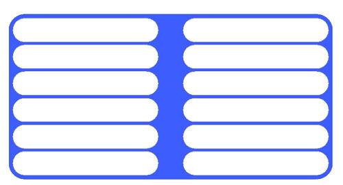
Figure 1: 2D heat exchanger - Type 1
2D Heat Exchanger: Type 2
This geometry is also a 2D extract of shell-tube-heat exchanger. In this case shell and tube is of circular shape. For this geometry both shell and tube side fluid mesh is to be created.
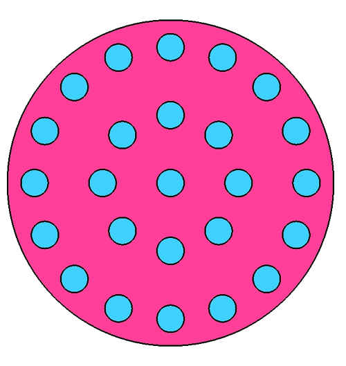
Figure 2: 2D heat exchanger - Type 1
3D Heat Exchanger
This geometry is a 3D shell-and-tube heat exchanger geometry. The shape of heat exchanger is rectangular and mesh for both shell and tube side fluid is to be created.
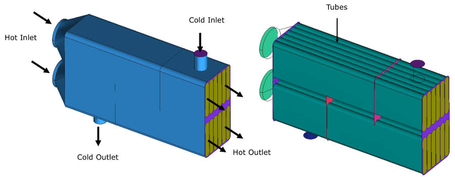
Figure 3: 3D heat exchanger
Counter Flow Heat Exchanger
This geometry is a 3D shell-and-tube heat exchanger geometry with counter flow arrangement. Both shell and tube side fluid mesh is to be created.
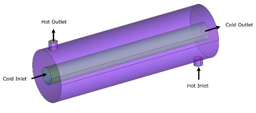
Figure 4: Counter flow heat exchanger
Cyclone Separator
This is simple cyclone separator geometry. The dust collecting hopper is not included in this geometry and has only top surface on dust collector.
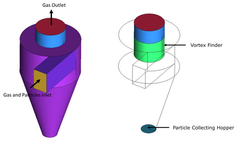
Figure 5: Cyclone separator
Office HVAC Duct
A typical building HVAC system contains AHU (Air Handling Unit), supply ducting, supply nozzles and/or diffusers, return grills and return ducting. This geometry is an extract of complete HVAC system for office space. It only includes supply ducting for four office room.
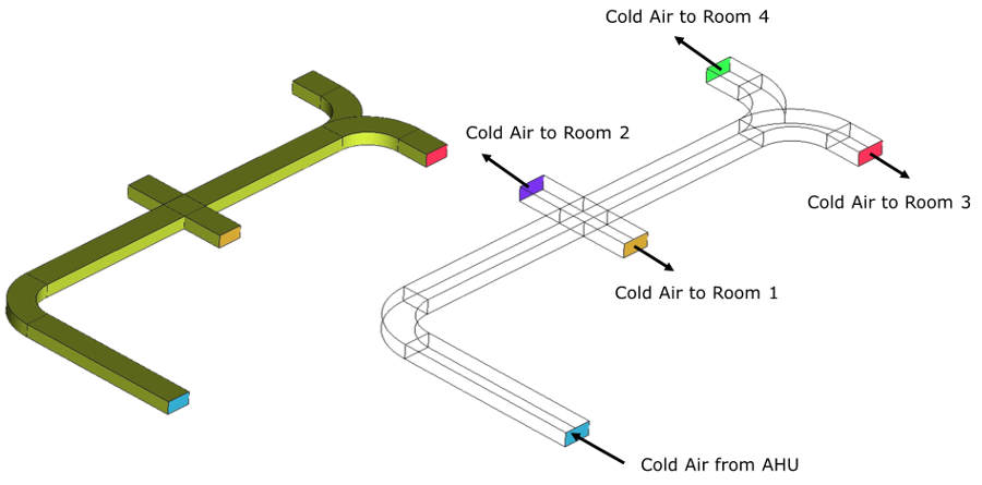
Figure 6: Office HVAC duct
Engine Silencer
This is a typical geometry of engine silencer. In actual condition, the engine silencer would contain many internal components to attenuate the sound generated by engine. In this geometry all internal components are removed and a plane silencer geometry is given. The objective is to create a mesh for flow analysis inside a silencer.
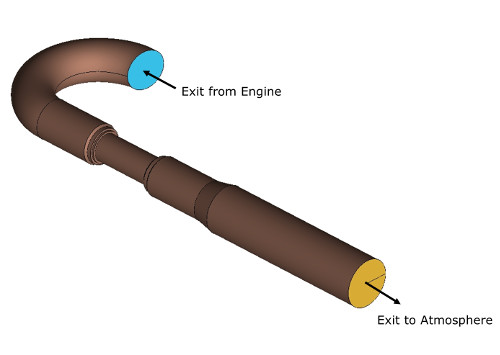
Figure 7: Engine silencer
Solar Dryer
Solar dryers are utilizes solar energy to dry items like grapes, fish etc. Solar energy is collected using solar collectors, and supplied to air. This heated air is then passed through solar dryer containing food items. The hot air is passed through inlet channel and distributed over drying tray placed in drying section. The number of trays depends on quantity of food to be dried and amount of hot air available. Uniform flow distribution at inlet of drying section is critical factor for optimum performance of dryer.
The given geometry is one of such solar dryer. This geometry contains only inlet channel, drying section and outlet channel. All the trays are modeled with zero thickness walls. The objective is to create a mesh for flow analysis.
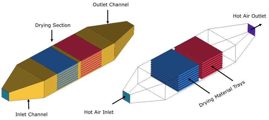
Figure 8: Solar dryer
T-Section
This is simple T-connection used in typical piping system. It has two inlet branches and one outlet branch.
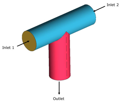
Figure 9: T-section
Download Other Files
Links to download a PDF copy of this document is provided below for your future reference. It’s a compressed zip file. Download and unzip the file will get a PDF copy of this document.
You can also download both the files from “Shared Files” section on lesson page.
Results and Discussion
If you have any specific query about the mini project or want to share the results of this project, please post them on course discussion forum.