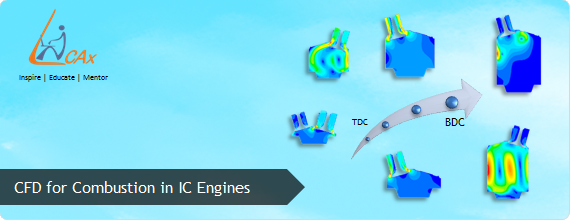
Insights on CFD for Combustion in IC Engines
In the earlier blog Combustion in Internal Combustion (IC) Engines we had an introduction about the combustion phenomena taking place in an automotive IC engine. The present article is an effort in continuation to have insights on CFD of combustion in IC engines. As we know the key factors that govern the decision making of any automobile buyer in general are, its mileage, performance, maintenance and tentative life apart from passenger comfort and aesthetics. An engine forms the heart of an automobile that can dictate its performance and life and is solely governed by the combustion pattern inside. The detail analysis of combustion in any engine is one of the most important key factors to confirm its efficient design wherein computational fluid dynamics (CFD) proves to be an efficient tool.
The factors governing the combustion process in any automotive engine are as follows:
For Spark ignition engines (SI) :
- Spark timing : It is the instant at which spark is provided to ignite the air fuel mixture. Spark timing affects peak cylinder pressure and temperature of burned gases.
- Valve timing : Valve timing typically means opening and closing of intake and exhaust valves during operation of engine.
- Mixture composition near spark plug : Mixture composition is the most important factor in governing the combustion process and its development
For compression ignition engines (CI) :
- Fuel injection parameters :
a) Fuel injection timing : the time at which fuel is injected in the combustion chamber
b) Fuel injection pressure : pressure at which the fuel is injected
c) Spray formation, mixing and combustion of fuel : governed by above two factors
- Temperature attained at the end of compression stroke : as combustion in CI engine completely depends on the self ignition of the fuel
Common parameters for SI and CI engines :
The common factors that affect combustion in both SI and CI engines of any automobile are :
- Air fuel ratio (AFR): This is the most common term one will come across while studying combustion, be it in IC engine or any other application. It is defined as the ratio of mass of air to mass of fuel.
a) For SI engine : AFR ranges from 12 to 18
b) For CI engine : AFR ranges from 18 to 70
- Compression ratio (CR) : It forms one of the most important design specifications of an IC engine. In simple terms it can be explained as the ratio of volume of combustion chamber at bottom dead centre to that of the volume of combustion chamber at top dead centre.
- Turbulence : Turbulence governs the mixing of air and fuel in the combustion chamber. CI engines are largely dependent on turbulence inside the engine for mixing purpose.
The study and evolution of heat engines dates back to about two and a half centuries, however it was since past seven decades it become a topic of greater interest due to modernization and industrial revolution across the world. There has been huge research going on the world over studying the effects of discussed parameters in combustion process. In early times the research approach was carried out by means of various iterations and modifications in the existing engine experimentally. The experimental approach however had limitations with long design cycles composing of many designs iterations, its manufacture, testing and then performance analysis. Finally if satisfied with the performance of made design, the engines are given a check, but if not then, studying the flaws in the design, correcting them, redesigning, manufacturing, testing and again performance analysis was carried out. The experimental approach thus proved to be delayed process and high on investment.
This is where CFD analysis proves to be a savior, evolving since 1940's as a powerful tool helping in designing and optimizing in almost every field of engineering. CFD with the help of computers and mathematical codes that define the physical processes, helps us understand and visualize the actual physical phenomenon.
How it started ?
In 1975, an influential workshop was held on the Numerical Simulation of Combustion for Application to Spark and Compression Ignition Engines. This motivated many researchers and initiated the development of combustion models for engines. Initially CFD modeling of combustion was carried out without any physical or chemical phenomenon due to the computational limits present during those times. An interesting research was published by J. B. Heywood (1994), in which he defined engine combustion model as physically based replication of the engine combustion process that can predict the mass burning, flame development and propagation. To have an update of the CFD capabilities and the evolution of computational simulation till 2005 one can go through an interesting read entitled “Computational Combustion” published in Proceedings of the Combustion Institute.
The challenges faced in CFD modelling discussed in popular literature are as follows:
- Study of laminar and diffusion flames at high pressures
- Soot kinetics
- Burning of droplets
- Radiation
- Flow through intake and exhaust valves
Los Alamos, Lawrence Livermore, and Sandia, all these US laboratories have extensively worked in computational domain for combustion modelling. Interestingly the scenario has changed due to large computational capacity of computers as well as development of various models that can now-a-days predict results quite near to physical phenomenon.
How CFD does it ?
Every physical phenomenon taking place in an engine is backed up by the mathematical equations that are modelled with some assumptions and are solved on computers with inputs taken from the user. Although this may seem simple but is not actually, as the accuracy of any CFD analysis of combustion is hugely based on the selection of the models and these knowhow skills are acquired only after considerable experimental studies and computational modeling experience.
Let us see a simple algorithm to explain how CFD modelling is done:
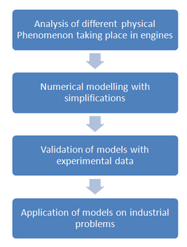
(Source: Turbulent combustion modelling by Denis Veynante & Luc Vervisch)
Combustion modeling in IC engine :
Different phenomenon that need to be modeled for the CFD analysis of combustion in an IC engines are listed below :
- Turbulence
- Injection
- Combustion (due to spark in SI engines/ self ignition in CI engines)
- Heat transfer
- Pollutant formation
Every above listed phenomenon is defined by a mathematically model which needs to be solved so as to simulate the problem with most accuracy. CFD simulates combustion based on the models selected and the basic requirement of a model is that it should solve the flow equations resolving chemical reactions. Chemistry coupling with the CFD solver is one solution to such a challenge however demands for larger CPU time. As described in the paper by Vincent Knop et. al (2008), the authors have rightly described these encountered complexities. As the quantities to be solved are the product of number of cells and number of species one can thereby right away guess the total number of quantities required to be solved. If this is still computationally manageable, imagine this with a finer mesh. To add to this in IC engines, the conditions change with progress in time, making the solution time dependent and expensive as well.
As already stated, the combustion modeling solution reliability solely involves proper selection of a combustion model that can accurately predict the complex physical process involving chemical reactions. The model applied should predict the chemical species formation and destruction rate, its concentration, and also changes in the temperature, density and enthalpy of the system. An IC engine working being time dependent, varied by number of parameters as well as cyclic variations, faces a lot of challenges for its modeling.
Challenges for modeling of IC engines :
The flow that takes place in IC engine is highly turbulent reacting flow, during which rapid combustion takes place. Hundreds of chemical species are formed and destroyed via thousands of reaction at a very fast rate. Resolving the chemistry- turbulence interactions and varied length and time scales, becomes a challenge.
Some of the challenges while CFD modeling of combustion are listed below :
- Moving mesh required to depict the motion of piston and valves : To accurately model the flow conditions valve and piston motion is required to be given to the mesh. This makes the problem complex, as moving mesh form computationally costly solution.
- Fine mesh required to resolve velocity, temperature and species gradients : This is required due to varying length and time scales, and for accuracy
- Spray modeling : In port fuel injection SI engine and in CI engines, accurate modelling of spray to resolve droplet size and breakup increases the accuracy
- Flow modeling : IC engine has highly turbulent flow conditions, due to high speed and modeling these flow conditions forms a challenge
- Combustion and pollutant modeling : Selection of proper model to resolve the combustion phenomenon and pollutant formation is a challenge
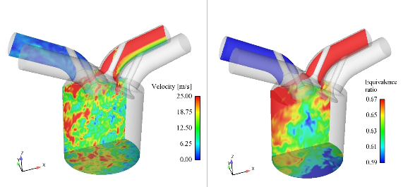
Another difficulty that may impede the accuracy of solution is choosing the reaction mechanisms. For example, when n-heptane completely burns, around 300 species are formed via around 3000 reactions. Involving such a detailed chemistry will cost a lot in terms of computational time and cost. A lot of study has been done to identify the critical reactions and reducing the overall mechanism. Such mechanism which include only critical reactions are called as “Skeletal mechanisms”. Below are a few images of CFD simulation in IC engines.
Let us go through an example to understand this. ConvergeCFD have come up with SAGE solver which is a multi-zone chemistry to decrease run times with minimal accuracy penalty. The SAGE solver has been developed by partnership with Lawrence Livermore National Laboratory. SAGE groups cells having similar temperature and equivalence ratio into zones. Chemistry is solved on these zones collectively rather than solving on each cell. Number of zones being much lower than the CFD cells, SAGE-Multizone greatly reduces the computational requirements for detailed chemistry.
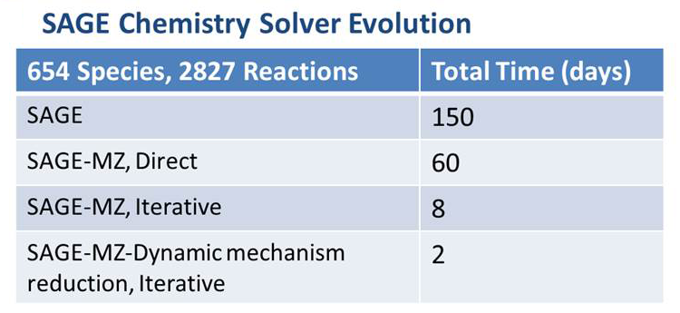
(This image shows the evolution of SAGE solver to solve 654 species and 2827 reactions. The total time in days have reduced from 150 to 2 for the recent version of SAGE. Source: www.convergecfd.com )
Algorithm concept courtesy- Turbulent combustion modelling by- Denis Veynante and Luc Vervisch
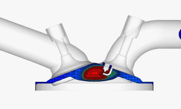
The below image clearly shows ignition taking place after the compression stroke, also can be seen is the varying mesh in the region a new technique is developed by Converge CFD and is called as Adaptive mesh refinement (AMR) (Source: www.convergecfd.com )
http://www.youtube.com/watch?v=mcJWK0N6i-o
The below video shows injection and combustion in a sector of diesel engine
http://www.youtube.com/watch?v=v1ulRr8ADhA
Also readers are recommended to check a very impressive post-processed combustion simulation video, that shows fluid flow in engine like geometry. A Direct Numerical Simulation (DNS) was carried out and VisIt visualization tool was used for flow visualization and animation
http://www.youtube.com/watch?v=opRC5T8cyLQ
Extent of CFD analysis in combustion :
If one goes through the wide literature available on CFD analysis in combustion being published in recently years there are pretty chances to be mesmerized by the developments in understanding combustion. Though there are many areas already explored but are there are still niche domains and some of the genre of these studies are as listed below.
- Cold flow simulation to visually understand the swirl and tumble generated
- Combustion modelling using different fuels
- Validation of in house developed CFD codes developed in house
- Modification in existing engine design
- Designing an engine combustion system from scratch
- Emission prediction
Future of CFD in IC engines :
In Advantage Magazine published (2012 Volume VI) by ANSYS Inc, there was an interesting article by Nazario Bellato, (Simulation Manager, Magneti Marelli) describing the use of ANSYS FLUENT to design and optimize the fuel injection system in the existing engines for the use of biofuels. CFD has already made its way in the conventional design process and this was just one example. With more and more advanced models developed and validated with experimental data, the accuracy of solutions obtained has been increased and hence CFD has become quite a dependable strategy. This was just a short attempt to you some flavour of application of CFD in IC engines. CFD is a rich field for people to take in research and as the time has shown, immense development is expected.
References :
- Computational combustion- Charles K. Westbrook, Yasuhiro Mizobuchi, Thierry J. Poinsot, Phillip J. Smithd, Jurgen Warnatz, 2005
- Modelling of combustion and nitrogen oxide formation in hydrogen-fuelled internal combustion engines within a 3D CFD code- Vincent Knop, Adle`ne Benkenida, Stephane Jay, Olivier Colin, 2008
- Combustion and its modelling in SI engines, J. B. Heywood, 1994
- Modelling of a fluid flow in an internal combustion engine, J.J.M Smits, 2006
- Turbulent combustion modelling- Denis Veynante and Luc Vervisch, 2001
- Advantage Magazine, Volume VI, 2012, by ANSYS
- www.cerfacs.com
- http://crf.sandia.gov/
- www.convergecfd.com
The Author
{module [317]}