Recirculation Boundary Conditions in ANSYS FLUENT
For solution of any computational fluid dynamics problem, initial and boundary conditions needs to be specified. Boundary conditions are essential component of a mathematical model. They direct the motion of flow which leads to a unique solution. In ANSYS FLUENT (or in general in any CFD software), we are familiar with standard boundary conditions such as inlet, outlet, wall, symmetry etc. These types are of boundary conditions are frequently used. But there are certain applications which require custom boundary conditions which are bit different from these standard boundary conditions. This blog will explain the use of one such “special” boundary condition called “Recirculation Boundary Condition”. This is specific to ANSYS FLUENT solver and is used for specific set of devices/problems.
Recirculation Boundary condition:
There are certain appliances wherein the working fluid is recirculated in the domain of interest from the outlet. The best example of this is car HVAC systems. The cold or hot air is recirculated in the enclosed domain. These recirculation devices have wide range of application areas, such as industrial buildings, housing complex, cars, laboratory clean rooms etc. These systems are effective in cooling / heating as the cold/hot air is reused.
Observe following image. We usually see a button with similar symbol in cars.

This button is for turning on recirculation mode of air conditioning system. This will cool your car faster and may save some fuel as well.
Building HVAC Example and CFD Problem
Let’s discuss in detail one of the example where recirculation of cold air is used. Imagine a case of building Heat Ventilation and Air Conditioning (HVAC). In typical building HVAC, a centralized air conditioning system is used. In such system, cooling of air is carried by set of Air Handling Units (AHUs) placed at one location. As per the cooling requirement, this cold air is supplied to different locations using a ducting system. The return ducting brings hot air back to AHU for cooling. The AHUs are generally controlled by measuring the temperature of return air. The cooling circuit in AHU has chilled water which is cooled somewhere else (typically cooling towers installed on the roof of building)
A schematic representation of such system is shown in figure below:
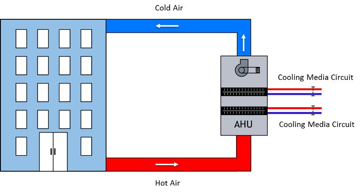
There are many ways to control AHU cooling. Some of the methods provides on demand cooling capacity, means if return air temperature is high, provide more cooling, and if less, provide less cooling. This is typically controlled using amount of chilled water. In few cases, AHU operates in ON/OFF mode with fixed cooling capacity/supply temperature. This means, if the return air temperature becomes too cold (set using some target temperature), the AHU goes OFF. It keeps on monitoring the return air temperature and goes ON if return air temperature is more that set temperature. In such configuration, AHU provides a fixed cooling (or operates at fixed cooling capacity).
For CFD simulation of building HAVC problems, focus is what happens inside the building (most of the time). The analysis is done to check if flow and temperature distribution inside the room is appropriate or not. What happens inside AHU is of no interest. It is allowed to make an assumption that the AHU provides fixed cooling (heat removal) for incoming air. It means, in CFD analysis we can assume that if incoming air is of temperature TReturn, the supply temperature of cold air would be TSupply = TReturn – (heat removed by AHU/ m * Cp), where m is mass flow rate through AHU and Cp is specific heat of air.
The schematic representation of CFD problem is shown in below figure:
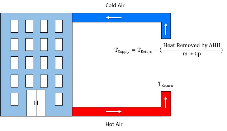
The main challenge in modelling above CFD problem is that TReturn is not constant. Return air temperature depends on the heating load inside the building and temperature of cold air supply (TSupply). Although AHU provides constant cooling (constant heat removal), TSupply depends on what is the TReturn. So in CFD problem definition, we cannot provide a fixed value of TSupply and TReturn. They depend on each other.
To model such CFD problems, following approach is necessary:
The first CFD solution iteration should be done with guess value of TSupply. After getting solution of iteration 1, area average value of TReturn should be calculated. Using fixed heat removal, TSupply should be calculated. This TSupply values should be used for next iteration. This process should be repeated till TReturn and TSupply values becomes constant (as we are doing a steady state analysis). Following flowchart schematic of this approach.

To implement above approach, what we need is the TReturn surface temperature values during each iteration. We need a method to calculate average value of TReturn and to calculation TSupply. We also need a method to update a TSupply value during each iteration. This is typically done using UDF (User Defined Function) in ANSYS FLUENT. Such UDF is not very complex to write provided that you have knowledge of C programing, how UDF works, how to compile and hook UDF to boundary zones. This can definitely done (For those who has interest in flowing this path, we have a separate set of blogs covering ANSYS FLUENT UDF).
What if I tell you that, you can do just same without using complex UDF? What if I tell you that it’s a simple setup of selecting a special boundary condition, and it will do the same thing specified in above flow chart?
Recirculation Boundary Condition in ANSYS FLUENT is just designed to do such jobs. Above cases is just one example. In general, Recirculation BC is used where you want to remove specific amount of heat before you recirculate the flow back to domain, if you want to specific a fixed amount of ?T between inlet and outlet. This type of boundary condition is always implemented in pair. For every recirculation inlet there is a recirculation outlet associated with it.
How to implement this boundary condition in ANSYS FLUENT?
In ANSYS FLUENT, recirculation inlet, outlet boundary conditions are not available by default. You have to enable them from TUI.
Following are the commands which are required to turn ON this boundary condition.
(rpsetvar 'icepak? #t)
(models-changed)
This boundary condition is very useful to model recirculation appliances such as heating or cooling devices. In such devices fluid is supplied from one section into the simulation domain, this section is usually referred as inlet (or supply). Fluid is extracted out from other section which is usually referred as outlet (return); this extracted fluid is returned/recirculated back to supply section. Before recirculating this fluid it could be cooled down, heated up or returned without any temperature change. This depends on the type of the device (heating/cooling device).
This boundary condition needs a pair of inlet and outlet zone. Following section gives details about the setup for inlet and outlet in the pair.
Conditions at Inlet (Supply)
Following inputs needs to be provided on the inlet partner of the pair
- Its outlet partner
- Temperature rise specification method
- Input for thermal conditions based on the temperature rise specification method selected
- Flow direction
- Other scalar properties bases on the models selected
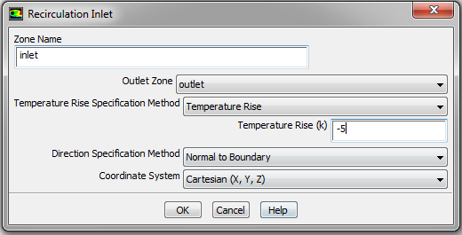
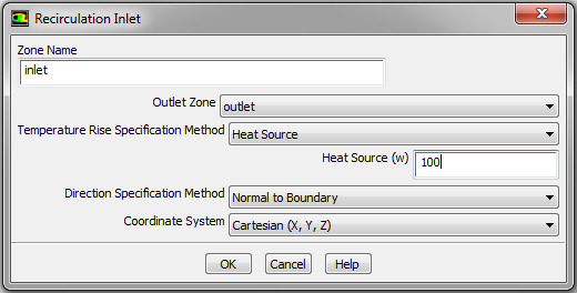
Following figures shows typical setup for inlet partner of the pair.
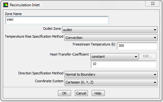
All other conditions including mass flow rate and thermal conditions are provided at outlet.
Conditions at Outlet (Return)
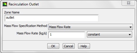
On the outlet partner of the pair, only mass flow needs to be provided. The mass flow can be provided using either mass flow rate or mass flux
1. Mass flow rate: We can specify total mass flow rate through supply section or extraction section. Following image shows snap shot of ANSYS FLUENT for specifying mass flow rate.
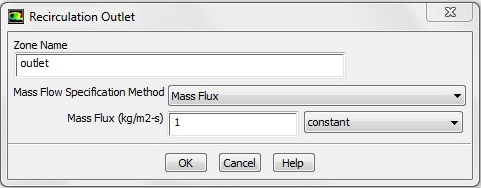
2. Mass flow rate per unit area (mass flux): Using this option we can specify mass flow rate per unit area. Following image shows snap shot of ANSYS FLUENT for specifying mass flux.
Thermal condition calculations
When the fluid re-enters in the enclosed domain, its temperature may increase or decrease. The inlet (or supply) temperature calculation depends on Temperature Rise Specification Method Selected. There are three methods by which we can specify the fluid supply temperature (TIN).
1. Temperature change/rise
In this method we can specify constant temperature change (ΔT) which is maintained with the help of heating or cooling device. TIN is calculated using following equation:
TIN = TOUT + ΔT
2. Heat addition or extraction
This method requires specifying amount of heat (ΔH) added or removed from the fluid by recirculation device. In this method TIN is calculated using following equation:
TIN = TOUT + [ ΔH / (m x CP ) ]
Where CP is specific heat of the fluid and m is mass flow rate of fluid through the device.
3. Convection
In this method we need to specify the external temperature (TExternal), product of heat transfer coefficient and area (h x A). Following equation shows the relation of TIN with other parameters.
TIN = TOUT - [ h x A x (TOUT – TExternal ) / (m x CP ) ]
So we have seen how to implement recirculation boundary conditions in ANSYS FLUENT. This is one custom type of boundary condition which is available in ANSYS FLUENT, but there could be some specific boundary conditions which are not available directly in ANSYS FLUENT. In such cases we can still implement those boundary conditions in ANSYS FLUENT using a User defined function (UDF). We will not go in details about creating custom boundary conditions using UDF in this blog. If you are novice to UDF then please visit our blog series on UDF.
Feel free to contact me in case you have any queries related to recirculation boundary conditions or any other custom boundary condition, I will try to resolve your queries to the best of my knowledge.
Reference
ANSYS User Guide
The Author
{module [312]}