Introduction to CFD – Part IV : Boundary Tagging
Different boundaries of regions require different boundary conditions. Applying boundary conditions in pre-processing tool is the process of putting appropriate tags (labels) on specific boundaries
Good labeling at pre-processing stage will be solution setup and pros-processing very effective. There are typically two types of boundary conditions (tags) we assign.
- Surface boundary conditions
- Domain (Regions) boundary conditions
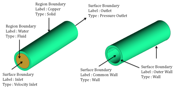
Let’s take an example of flow through cylinder with heat transfer across the thickness of cylinder. We need to specify following type of boundary conditions as the meaning and effect of each and every boundary conditions will be different
Surface boundary conditions :
- Inlet : To specify that flow is coming in through this boundary
- Outlet : To specify that flow is going out through this boundary
- Common Wall: A Wall between fluid (water) and solid (copper) regions. This wall should interact with both side domains (one side fluid and other side solid)
- Outer Wall : To specify convective heat transfer coefficient and free stream temperature
Region boundary conditions :
- Copper : Solid region to specify that only energy equation need to be solved using copper material properties
- Water : A fluid region to specify that continuity, momentum and energy equation need to be solved using water material properties
Why we need labeling (tagging or boundary conditions) in pre-processing stage ?
Geometry creation or grid generation is not at all going to be affected by different boundary conditions. The data provided on boundaries (example, velocity at inlet, temperature on wall, pressure at outlet, material properties etc.) is going to be used during solution of the governing equations. So by looking at solution methodology, it can be said that, boundary condition is not a part of pre-processing stage.
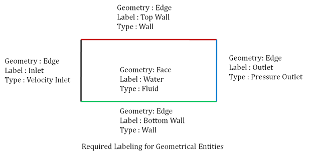
Although boundary conditions is not a part of pre-processing stage, we have to prepare the grid (mesh) in such a way that it will be easy for us to create solution setup and to do effective post-processing. Appropriate tagging will help you out during solution and post-processing. Now the question is why we do it at pre-processing stage and why not at solver stage. The answer to this question is straight “All the solvers takes only grid into it and carry out the solution. No solver understands the geometry”. In other way, the grid (or discritized geometry goes to solver) not the geometry. As the solver take grid, it will be very difficult for us to put some separate tags on different surface cells (quadrilateral or triangle) and separate tags for different volume cells (hex, tet etc.). To understand this concept, let’s take an example of 2D section of square duct. Imagine that we have created a quadrilateral mesh in the fluid region with a common tag on all edge.
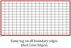
As the there is same tag on all the boundary edges, we can put only one type of boundary condition on them (either inlet or outlet or wall).
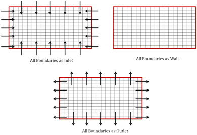
But the problem under consideration needs following boundary conditions
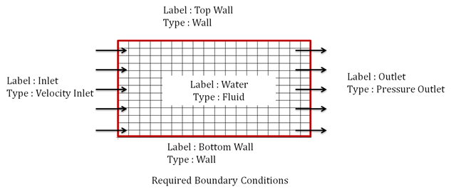
If the grid is created without any label on geometry entities (edge, surface or volume), there will be common label assigned. (For example all surfaces will have label “Wall” and all domains (regions) will have label “Fluid”). Once the grid is created without appropriate labeling, it will be very difficult if not possible to separate the specific surfaces (quad, tri) or volume (tet, hex) cells and to put appropriate tags (inlet, outlet, solid, fluid etc.) on them. So it’s better idea that we do tagging in pre-processing stage only. For above problem, following tagging will help us to put appropriate boundary conditions.
Tagging in pre-processing tool will take some time. But once it is done, the solution setup will be very easy as well as post-processing will be very effective. An inappropriate tagging may take lot of time only for solution setup and may have restrictions on post-processing. There are cases where because of inappropriate tagging; the mesh generated becomes useless (as the boundaries are not available for putting appropriate boundary conditions). So before creating the mesh, make sure that you have given appropriate tags as necessary by solution setup.
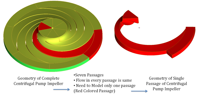
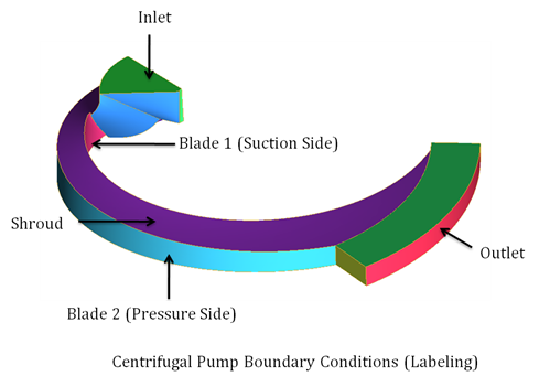
The typically used tagging for sector impeller is as shown below :
Following are the advantages of putting appropriate tags on surface as well as volume domains
- It will be visible as it is in solvers and it will make our solution setup very easy and effective
- If we put appropriate tags on boundaries, we can do very effective post processing
In fact, some of the tools like ANSYS CFX recognizes the tags in appropriate way and will provide standard functionalities for post-processing. For example, if we give the mesh of a sector of centrifugal pump impeller with above shown tags to ANSYS CFX, it can do the post-processing automatically. There are very good templates available in ANSYS CFX for turbo machinery problem setup as well as post-processing. The user just has to select the type of turbo machinery (Centrifugal compressor, centrifugal pump, fan etc…), ANSYS-CFX will select appropriate equations to be solved, appropriate solver for solving equation and so on. There will be very less inputs needed from user side. Once the simulation is carried out, ANSYS CFX can generate report automatically in HTML format with all the parameters (blade loading, isentropic efficiency, power needed etc.). This can be done very effectively, if we follow the standard labeling (tagging) method. So appropriate tagging is very important aspect of pre-processing
Once the appropriate tags are defined, we can apply respective boundary conditions. Following are the typical boundary conditions used by most of the commercial CFD solvers
Inlet Boundary Conditions :
- Velocity Inlet
- Pressure Inlet
- Mass Flow Inlet
Outlet Boundary Conditions :
- Pressure Outlet
- Outflow
Domain Boundary Conditions :
- Fluid
- Solid
Special Boundary Conditions :
- Symmetry
- Periodic
- Interior
- Axis
Even if above boundary conditions are not defined in pre-processing tool, it can be done very easily in solver provided that the appropriate tags are defined.
Exporting the mesh :
Once the appropriate mesh is created, it can be exported for solution in different solvers. Many of the commercial tools provide functionality to write the mesh is specific solver format. Following are the few solver mesh formats
- ANSYS FLUENT – msh format (*.msh)
- ANSYS CFX – cfx format (*.cfx)
Even if the direct mesh export is not available, we can always export mesh in general format. The general format of the mesh is called as CGNS (CFD General Notation System). Almost all CFD commercial software has CGNS import facility through which we can take mesh into the solver.
To summarize, following are the steps that we will be doing in pre-processing :
1) Domain Definitions
- Geometry creation or geometry import
- Geometry cleanup
- Removing the parts not necessary for simulation under consideration
- Closing the gaps in the geometry
- Removing small surfaces, curves to make meshing process simple
2) Labeling (Putting Tags)
3) Mesh generation
4) Exporting the mesh for solver
The Author
{module [311]}