Introduction to CFD – Part III : Grid Generation
In simplest form, the grid generation can be defined as: “The process of dividing the given physical domain into smaller sub domains (called as cells or elements)”. There are various methods of creating the grid or mesh.
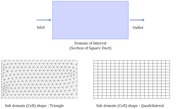
Figure below shows the grid for simple domain :
Domain selected: Region between four straight lines (Section of square duct)
Shape of sub domain (Cell) selected: Case 1: Triangle and , Case 2: Quadrilateral (Rectangle)
Following are the important properties of any gird :
- The shape you are selecting (may be triangle, quadrilateral, tetrahedral, hexahedral etc), must be completely understood by the equation solvers as we are giving grid as input to solver
- All the sub domains (cells) should cover entire domain completely
- The sub domains near the boundaries show be small enough to capture the curvature of boundary if any
- All the sub domains (cells) should be properly connected to its neighboring sub domains (cells)
- No two sub domains (cells) should overlap
- The layout of sub domains (cells) should be appropriate to captures the geometry features (curvature and proximity) and to capture the flow features (flow separation, wake ect.)
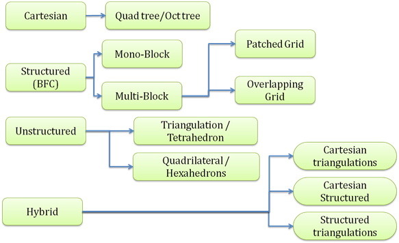
There are various methods of diving giving domain into small sub domains (cells). On broad level they are classified into four categories :
- Cartesian grid generation methods
- Unstructured grid generation methods
- Structured grid generation methods
- Hybrid grid generation methods
Following chart give layout of most popular grid generation methods :
Why Grid is needed ?
Very soon we will see the way the governing equations of given physics will be solved. To solve the governing equations, we use numerical methods like Finite Different, Finite Volume or Finite Element Method. All these methods are going to solve the discritiezed form of governing equations. The overall idea of all these methods is “Rather than solving the complicated equations on very complicated domain, divide the domain into small parts and solve the equations on one part at a time”
As we are going to solve the discritized form of governing equations, we can not solve them on continuous geometry (complete geometry at a time). So we have to also divide the geometry into small parts. This division of geometry in small parts is called as grid generation.
The grid generation is also called as
- Discritization of geometry
- Mesh generation
- Element generation
- Domain decomposition
All the above terms are synonyms for grid generation. As the grid generation plays very important role in quality of solution, we have to worry about following aspects of grid generation
a. Shape of sub domains (Cells) :
As the basic definition of grid generation allows us to select any type of the shape, the selection of shape determines the quality of solution we will be getting. On broad perspective it is seen that good distribution of quadrilateral or hexahedral cells aligned with the flow direction will give high quality results as compared to triangular or tetrahedral shapes
b. Size and distribution of sub domains (Cells) :
The smaller the size of cell, the better the numerical solution results will be. But as we are going to use computers to carry out numerical solution, we cannot have very small size cells. The amount of computer memory (RAM) needed for carrying out the solution is directly proportional to the number of cells. As we will be using limited memory computers (may be 3 to 4 GB RAM in case of desktops and 16 to 20 GB RAM in case of very good workstations), we have to make sure that number of cells generated will not be very huge so that it cannot be handled by computational resources we have. For moderately complex geometries, one can imagine to end up with 4-5 millions of cells. In case of very complicated geometries and flow physics one can imagine ending up with number of cells more that 10 million.
As we have limited computational resources, we have to make sure that we are using them effectively. This is typically achieved by putting small size cells in the region where they are needed and large size cells in the region where they are not needed. This is called as “Clustering”. The small size cells are needed to either capture geometry features (curvature or proximity) or to capture flow features (flow separation, shock waves, wake region etc.). The overall idea is put smaller size cells in curved geometry where we need to capture the curvature and put bigger size cells in the planer region. Similarly, put small size cells in boundary layer (where viscous effects are predominant – velocity gradient is high) and bigger cells away from the boundary
c. Size Change :
As we have discussed in previous point, we will be using smaller cells in the region where they are needed and bigger cells in the regions where the feature are not pre-dominant. While doing this, we should also make sure that, we are doing smooth transition from small size cells to big size cells. If there is sudden jump in the size of cell, this will give rise to error into your numerical solution
d. Quality of sub domain (cell) :
It is seen that the equilateral cells (equilateral triangle, square, equilateral tetrahedral, cube etc.) will give best quality results. These kinds of cells will have less numerical errors. It is not always possible to divide the domain into to equilateral sub domains (cells). This may be possible to do in very trivial cases like square duct or cubical room. But if the geometries are very complex (flow over car, flow through centrifugal pump), dividing the regions into equilateral cells will be almost impossible. In general, the term “Skewness” is used to compare the given cell with respective equilateral shape. There are many skewnees criteria which will compare some aspect of cell to its equilateral shape. Following are some of them
- Angle skewness – Compares the maximum/minimum included angle with equilateral angle
- Edge Ration – Compares the maximum/minimum edge length with equilateral edge length
- Area – Compares the area of given cell to the average area of all the cells
- Volume - Compares the volume of given cell to the average volume of all the cells
- Diagonal Ratio – Compares the maximum/minimum diagonal length (in case of quadrilateral of hexahedral element) to its equilateral diagonal length
- Aspect Ratio – Gives the idea about elongation of given cells
Each quality criteria compares some aspect of given cell to its equilateral counterpart. For given flow problem, we use the few of the quality criteria to make sure that the gird we have created is appropriate to capture given flow physics.
There are many kinds of cell shapes that people use. The shape of the cell is mostly decided by the type of solver we have. Whatever shape of cell that we are createing should be completely understood by the solver we are planning to use
Following are the typical shapes many CFD solver supports :
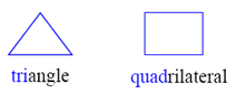
2D Shapes
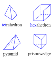
3D Shapes
Each type of cell has their own advantages are disadvantages. Recent developments in the solver are also supporting the polyhedral cells. Which type of cell and which type of the grid generation method to be used, depends lot on following aspects
- The desired accuracy of solution
- The complexity of shape of domain
- The time available to execute the problem
- Computational resources available
- Software tools available
Following are some of the snap shots of geometries meshed with various meshing approaches :
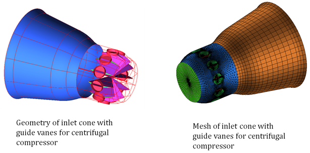
Case 1: Inlet cone for centrifugal compressor
Domain: Turbo machinery
Meshing approach: Mixed (Unstructured for guide vanes and structured for conical inlet)
Shape of cells: Tetrahedral, Hexahedral and pyramids (Transition between tet and hex)
Tools used: Geometry Creation: Pro Engineering | Meshing: ANSYS ICEM-CFD
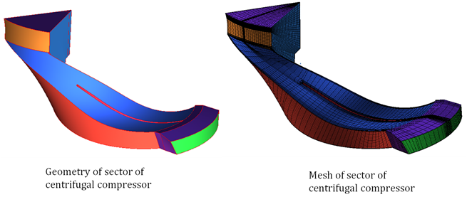
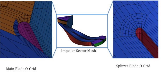
Case 2: Sector of centrifugal compressor
Domain: Turbo machinery
Meshing approach: Structured Multiblock hex mesh
Shape of cells: All Hexahedral
Tools used: Geometry Creation: Pro Engineering | Meshing: ANSYS ICEM-CFD
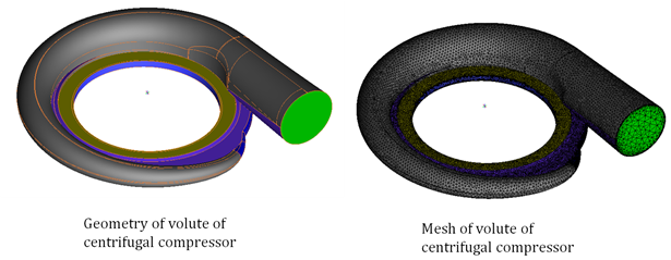
Case 3: Centrifugal compressor volume
Domain: Turbo machinery
Meshing approach: Unstructured
Shape of cells: All tetrahedral elements with prism elements in boundary layer region
Tools used: Geometry Creation: Pro Engineering | Meshing: ANSYS ICEM-CFD
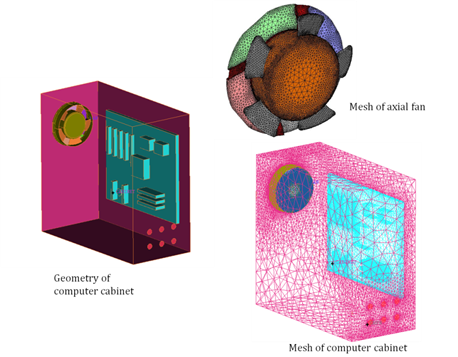
Case 4: Computer Cabinet
Domain: Electronic Cooling
Meshing approach: Unstructured
Shape of cells: All tetrahedral elements with prism elements in boundary layer region
Tools used: Geometry Creation: SolidWorks | Meshing: GAMBIT
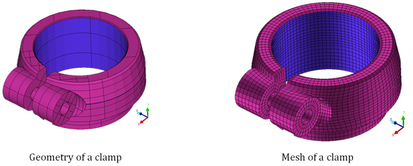
Case 5: Clamp
Domain: Structural Analysis
Meshing approach: Structured
Shape of cells: All Hexahedral
Tools used: Geometry Creation: SolidWorks | Meshing: ANSYS ICEM-CFD
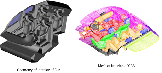
Case 6: Interior of CAR
Domain: Automobile
Meshing approach: Unstructured
Shape of cells: All tetrahedral elements with prism elements in boundary layer region
Tools used: Geometry Creation: CATIA, Meshing: ANSYS ICEM-CFD
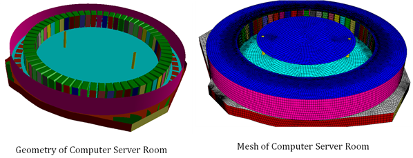
Case 7: Computer server room
Domain: HVAC (Heat Ventilation and Air Conditioning)
Meshing approach: Unstructured
Shape of cells: All hexahedral elements
Tools used: Geometry Creation: GAMBIT | Meshing: GAMBIT
The Author
{module [311]}