Introduction to CFD – Part II : Selecting the Domain
Understanding of the word CFD changes from person to person and from profession to profession. A CFD software developer understands CFD as method of solving governing equations using some numerical methods.
A CFD application user understands CFD as three step process involving pre-processing, solution and post-processing. All these understandings are correct by looking at activities that they will be involved in. Before going to all these aspect of “CFD”, let’s have a look at the basic definition of CFD. For the same, let’s break the word “Computational Fluid Dynamics” in to two as “Computational” and “Fluid Dynamics”
- Computational : Something to do with computers and numerical methods for solution of governing equation
- Fluid Dynamics : Something to do with physics of fluid dynamics and governing equations for the same. (Understand that, now a days the CFD tools are so much developed that they are also used to understand/simulate physics other than fluid flow like heat transfer, chemical reactions and many other)
So CFD in its simplest for can be defined as “A technique of solving governing equation of different physics like fluid flow, heat transfer, mass transfer and related phenomena using some numerical methods like Finite Difference Method (FDM), Finite Element Method (FEM) or Finite Volume Method (FVM)”
CFD for an Application Engineer :
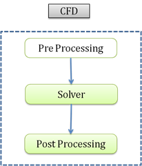
Application engineer is the one who uses available commercial software (or in-house research codes) to solve the engineering problems. Very rarely, he/she will be involved in writing the programs (codes) to solve the governing equations. Application engineering looks at CFD as three step process
- Pre-Processing
- Solver
- Post-Processing
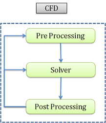
All the above steps are essential parts of any CFD project. In pre-processing stage, we will be creating the geometry and mesh along with appropriate boundary conditions. In solution stage (solver) we will be carrying out the solutions of desired governing equations. Once the solution is available, in post-processing stage, we will be visualizing the results using color plots, contour plots, velocity vectors etc. to understand the physics.
Let’s briefly go through the task involved in each and every stage:
Pre-processing :
There are three main tasks that we do in pre-processing stage
- CAD or Geometry Creation: Defining the domain where the solver will solve the governing equation.
- Grid Generation: Dividing the domain in small parts.
- Boundary Conditions : Applying appropriate labels (tags) on domain and domain boundaries
1. Defining the region (in space) of interest (Domain Definition) :
Defining the domain of interest is something to do with providing information to software about in which region the equations need to be solved. This task might be very trivial for simple cases like flow through pipe or flow over flat plate. But for very complicated cases like flow over an aircraft or automobile, this task itself takes considerable amount of time.
The domain definition depends mainly on the physics involved in the problem and aim and objective of the problem. To explain more about this lets consider some of the cases
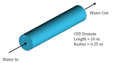
Example 1: Flow through pipe :
Objective: To find pressure drop across inlet and outlet
Fluid flowing: Water
Solid Material: Aluminum
Dimensions of pipe: Length = 10 m, inner radius = 0.25 m, thickness = 0.05 m
The aim and objective of above problem is to find the pressure drop across inlet and outlet. If we go back to the fundamentals of fluid flow through pipe, we conclude that pressure drop happens because of viscous effects (friction between fluid and wall of the pipe). The variation of the pressure is only governed by viscous effects (in case of incompressible flow which is valid assumption for water flow) and viscous effects happen only because of no-slip condition between pipe wall and water. It means that, the thickness of the pipe is not going to affect the calculation of pressure drop across inlet outlet. It means, if inlet and outlet boundary conditions, length and inner radius of cylinder are remaining same, the pressure drop calculation is independent of thickness of cylinder. Hence for this problem, the domain of interest will be only the fluid domain (wherever there is water present) and we will be interested in solving equations only in inside part of the pipe.
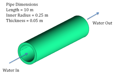
Actual geometry of pipe

CFD domain
Example 2: Flow through pipe :
Objective: To find the temperature and pressure drop across inlet and outlet of hot water carrying pipe kept in cold atmosphere
Fluid Flow: Water
Solid Material: Aluminum
Dimensions of pipe: Length = 10 m, inner radius = 0.25 m, thickness = 0.05 m
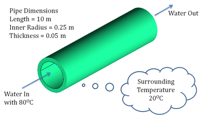
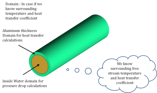
The aim and objective of the problem is to find pressure and temperature drop across inlet and outlet. The domain need to be modeled for pressure drop calculation has same considerations as discussed above. We need to model the fluid (water) domain for the same. In this case along with pressure drop calculations, we have to also calculate the temperature drop. Let’s discuss the physics of temperature drop. Let’s assume that water with 80OC comes into the pipe. Let’s assume that surrounding atmosphere temperature is 20OC. As the surrounding atmosphere is colder than the water, heat will flow from water to the atmosphere through thickness of the pipe. In this case, the thickness of the pipe also plays important role as the amount of heat moving out the pipe also depends on resistance provided by pipe material. So in this case, we have to model solid (aluminum) domain.
Fluid domain for pressure drop calculation
In this particular case, we have to also give considerations to surrounding atmosphere as the surrounding atmospheric temperature will also decide how much heat is moving out/in to the water through aluminum. If we need to model the part of surround or not depends on what kind of data known to us. In case where we know only surrounding temperature, we have to model some part of the surrounding so that the natural convection around the pipe can be modeled. The size of the surrounding depends again on the physics involved. Various literatures available will help us out to decide about the size of the domain.
In above case we have to model three domains:
- Water Domain : For pressure drop calculation
- Aluminum Domain : For resistance provided by solid part
- Surrounding air Domain : For heat transfer to the air
![]()
Domain for pressure drop as well as heat transfer calculation
But if we know the outside surface heat transfer coefficient (may be through some experimental study or through analytical correlations), we need not to model the outside pipe domain.
Domain is specified to any pre-processing tool using CAD (Computer Aided Design) model. If the domain geometries are very simple (pipe, flat plate, sphere etc), creating the CAD model is a very trivial job and we can use the functionality available in a standard pre-processing tool itself for creating the CAD model. But if the domain shape is very complicated (flow over car, automobile under hood analysis, flow through centrifugal pump, flow over aircraft), it will be very difficult if not impossible to create such kind of CAD geometries using standard pre-processing tools. In such cases, use of dedicated CAD software will be unavoidable.
Following are the typical steps that a pre-processing engineer will do:
- Create the CAD model in dedicated CAD software like ProE, CATIA, SolidWorks
- Export the CAD geometry in standard file formats like IGES, STEP, Parasolid using export facility of CAD software
- Import the CAD geometry in pre-processing tool using import facility of pre-processing tool
- Cleanup the geometry to reduce the complexity for meshing and to make watertight geometry
Any one of the above may take considerable time depending on the complexity of geometry or strength of import/export facilities available.
The Author
{module [311]}