Electrostatic Precipitators (ESP) Analysis Using CFD
The particulate emissions from process industries has received great attention due to the upcoming strict environmental protection agency (EPA) regulations and conservation in recent years. The Electrostatic precipitators (ESP) since its development in 1907 by Frederick G. Cottrell (Professor of chemistry at the University of California, Berkeley) have been the most common, effective and reliable technologies for removal of hazardous emissions like flue gases, acid droplets and fine particles.
The industrial ESP are capable of handling large gas volumes with a wide range of inlet temperatures, pressures, dust volumes and gas conditions and exhibit complex interaction mechanism between electric field, fluid flow and particulate flows.
Electrostatic precipitators
Working principle of ESP :
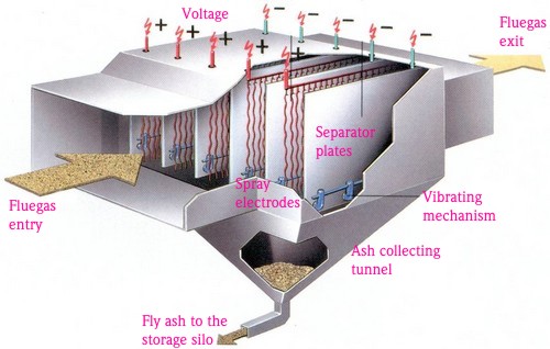
Electrostatic precipitators are used for reducing pollutants from the discharge (outlet) line of process industries and are generally installed in the ducts that discharge the flue gases into the atmosphere. The particulate matter in the emissions contain electric charges as they pass out of processes within reaction chambers, combustion chambers, etc and are negatively charged.
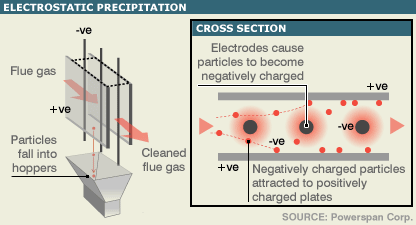
Working principle of ESP
Taking advantage of these charged particles, a set of positively charged sheets is inserted inside the device in order to attract the particulates. As the flow passes over the parallel set of sheets, the particles get attracted towards the sheet and get stuck over there. After some time of operation, the sheets get covered by a layer of such particles, at that moment the sheets are vibrated which causes the attracted particles to fall down and get collected in the bottom, i.e. in the tapered shape collection zone. Once this zone is sufficiently filled by such particulates, the bottom door is opened and the whole slug is removed out of the ESP. Hence, by the application of electrostatic force these pollutants are pulled out of the exhaust gas. This whole process is carried out inside an ESP and hence by reducing pollutants (carbon content majorly) a more eco-friendly gas is rejected into the atmosphere.
CFD as a design tool for ESP :
ESP though helps us to prevent pollutants from entering the atmosphere also actually adds to the operational costs in the industry & hence its very important to have an efficient ESP. An efficient ESP can be one that requires minimum electrical energy to separate out the charged particles of the bulk gaseous waste. Further understanding the physics of the process, one just needs to minimize the force required to attract & separate out the particulates by reducing their kinetic energy resulting by decreasing the flow velocity.
The flow velocity can be reduced by increasing the cross sectional duct area that may further result in change of flow distribution pattern. This then, becomes an important point to study as to how uniformly the flow pattern is ? This can be a very good CFD study & let’s discuss here a case study to better understand the CFD work.
Objective of study : To separate out maximum particulate pollutants with the minimum amount of power input.
From the velocity of the particles, we can find out the kinetic energy they possess. Based on this force, we need to generate an electrostatic energy (from the electrodes inside the device) of a higher magnitude than the kinetic energy of the particles in order to successfully remove them out of the flow. As the target is to minimize the energy required, it is obvious that we reduce the velocity of the flow as much as possible. It is equally important to have uniform & optimum velocity throughout the device. This means, velocity should not exceed the threshold value anywhere inside the device. If velocity exceeds the max permissible value then, particles will not get trapped and hence escape into atmosphere. At the same time if at some place, the velocity is too low then the particles will get collected at the beginning of the device itself and the energy supplied to the electrode sheets which are towards the end of the device will just go wasted. Hence it is very essential to maintain uniform velocity throughout the device.
In order to maintain uniform velocity one needs to have a good design of the device as well as entry and exit evase. Here CFD plays a very crucial role in testing and validating the designs.
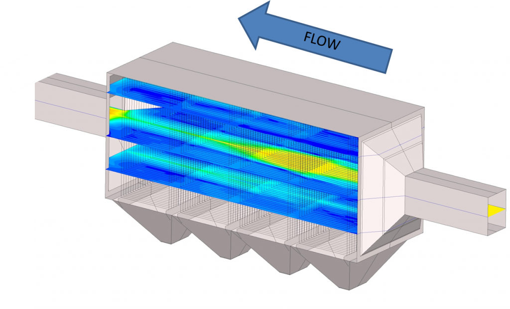
Electrostatic Precipitator Device :
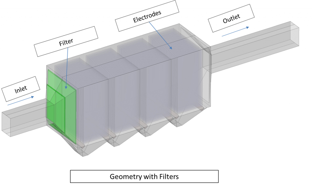
A simple demo case presented here was designed on the basis of space availability and hence it is quite visible in the geometry image (seen below) that this design is not an optimized one. There is an expected flow-separation at the inlet which is easily visible, but in order to predict this design’s ineffectiveness a complete CFD simulation needs to be done and based on the results the design will be optimized and another CFD study is conducted on the modified design. The CFD study will contain a very basic flow prediction inside the device. The discrete pollutants being so light in weight, that they won’t be influencing the flow behavior at all. Hence, the discrete pollutant phase is not modeled in this study and instead just air is modeled. The velocity prediction would give the understanding of the effectiveness of the device.
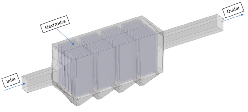 Geometry of a typical ESP
A steady-state single phase simulation was carried out with Reynolds-averaged Navier–Stokes equations coupled with the k-epsilon turbulence model equations. Default convergence criteria of 10-3 for all the equations were considered.
CFD Results :
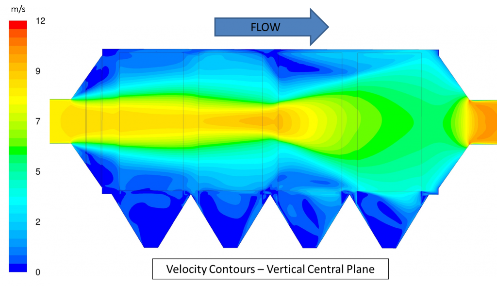
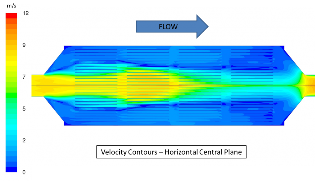
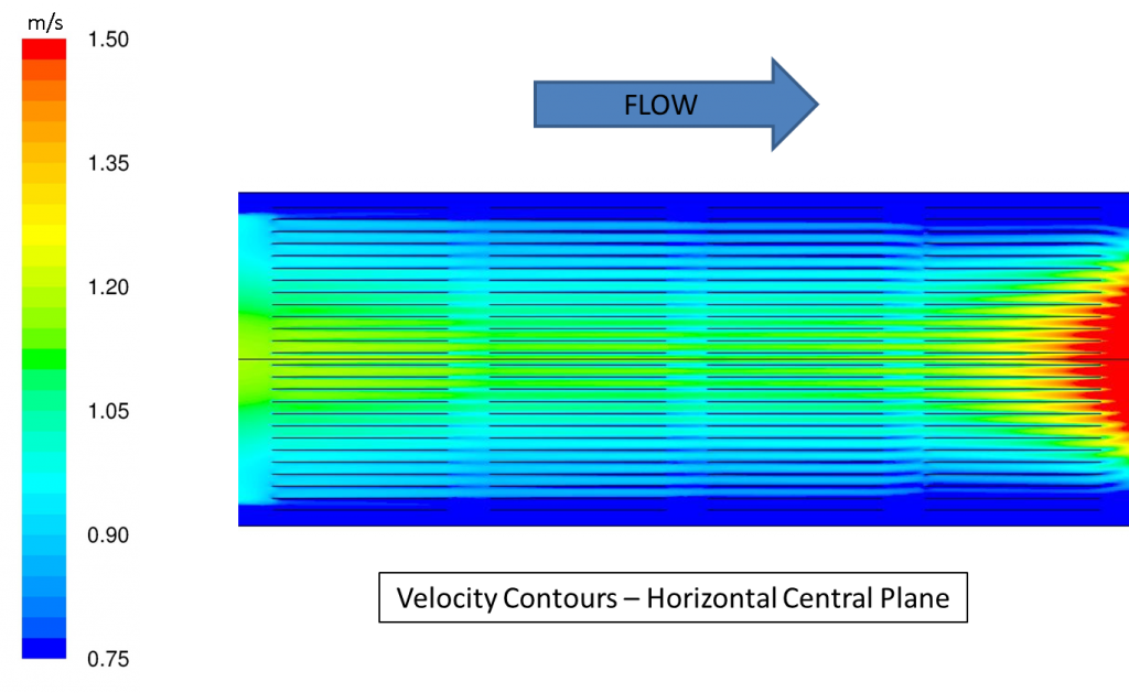
Let us have a look at the analysis data. The images below clearly show the non-uniformity in the velocity distribution inside the ESP Device.
Non-uniform flow distribution in ESP
In this setup, the available power was just sufficient enough to separate the particles (from the bulk flow) having velocities of 1.5 m/s or below. The following images will explain it in detail.
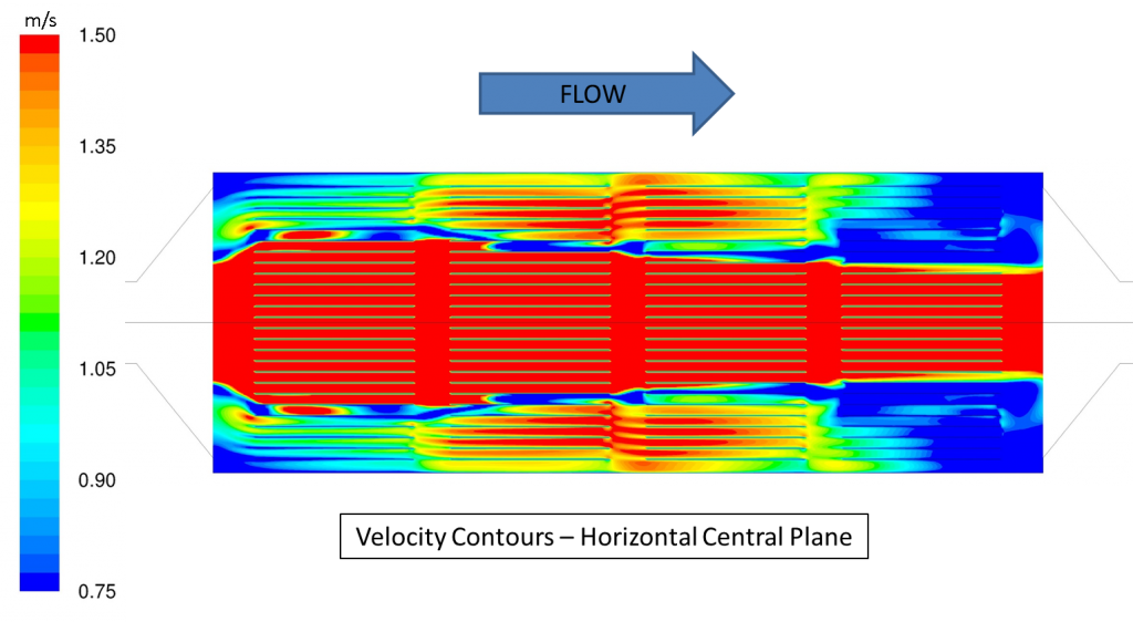
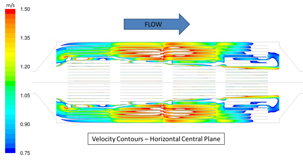
In the above images, can be clearly seen that in the colored zone the velocity is within range and the centre part (i.e. unfilled area) indicates that the velocity is not in operational range of the device. The percentage of area falling within the operational range is about 38% and 10% in horizontal and vertical cross-section respectively. This means that only around 25% pollutants would be removed from the exhaust gases whereas the energy supplied to it was sufficient enough to remove them completely. This gives an idea about how important role a proper design plays in each and every engineered product.
Non-uniformity in velocity distribution was observed within the device due to the sudden expansion of the duct which caused a flow-separation at the divergence section of the inlet. It would have been much more uniform if the increase of cross sectional area was done gradually, however though at times the decision is based on purely non-technical factors like space availability & others.
Optimization study :
In the existing design, a steel wire-frame (filter) was introduced at the entrance of the ESP to assist in the uniform distribution of flue gases.
The CFD approach was kept same as that of baseline study performed earlier, except the filter section that was modeled as a “porous zone”. Let us now analyze the results from the simulation study of this modified geometry.
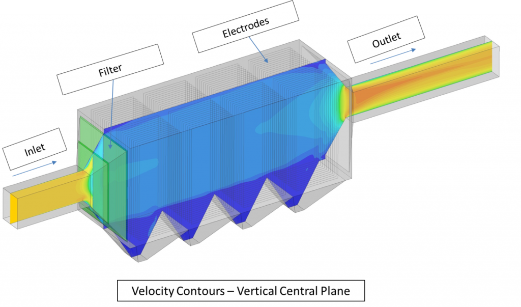
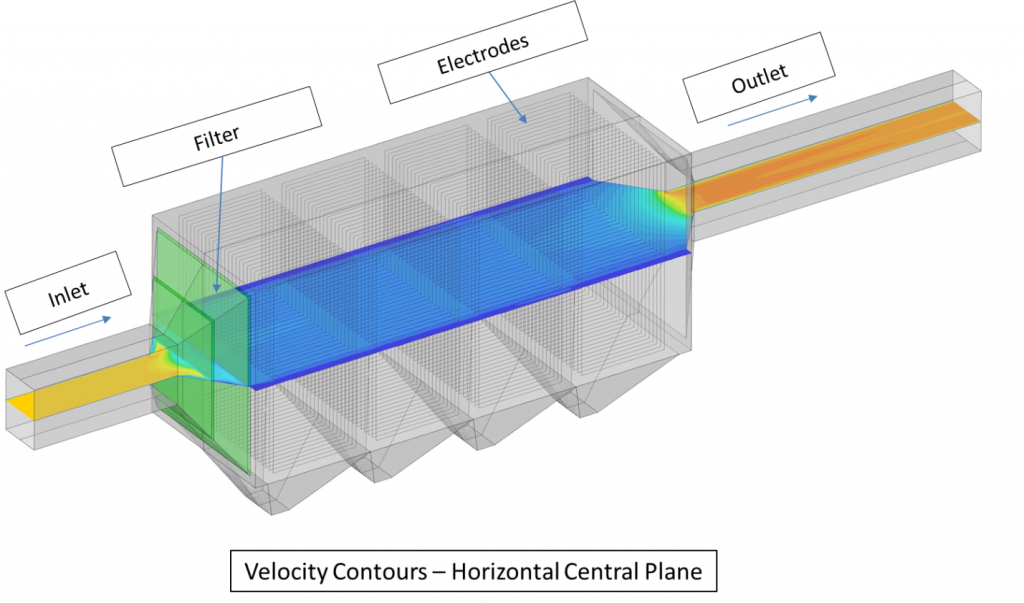
The above images have made it clear that the flow has become much more uniform than earlier. Now let us analyze it more quantitatively.
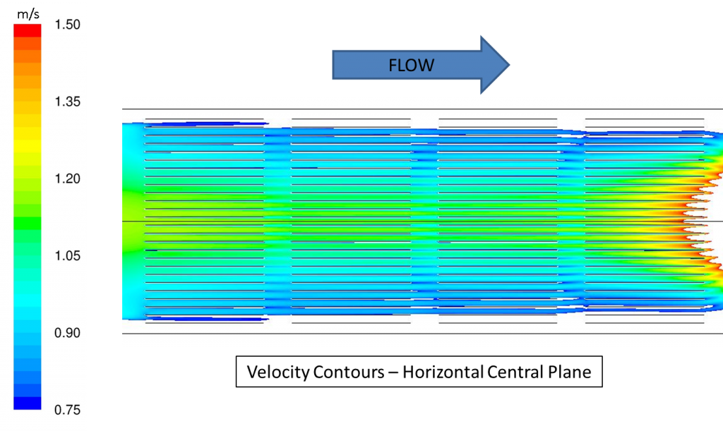
The above images display the area which falls in the optimum working range of the ESP. The percentage area comes out to be 99%. This clearly states that the efficiency of the device has increased from 25% to around 95% and above.
Also below is shown the video animation of the flow distribution in a ESP with and without filter:
|
{modal index.php/en/?option=com_content&view=article&id=104}
 {/modal} {/modal}
{modal index.php/en/?option=com_content&view=article&id=104}
 {/modal} {/modal} |
Summary :
The initial design of the ESP was studied with the help of commercial CFD tool “ANSYS Fluent” and after understanding its ineffectiveness, the design was modified by the addition of a filter. The insertion of filter at the inlet helped delay the flow separation at the inlet evase and improved the distribution of velocity in a more uniform pattern around all the electrode plates thus improving the efficiency of the ESP from 25% to 95%. Hence, CFD has proven as a very cost effective and useful tool in designing the Electrostatic precipitator.
References :
- Zhengwei Long, Qiang Yao Ã; Evaluation of various particle charging models for simulating particle dynamics in electrostatic precipitators Journal of Aerosol Science 41 (2010), 702–718.
- F.J. Gutiérrez Ortiz, B. Navarrete, L. Cañadas; Dimensional analysis for assessing the performance of electrostatic precipitators Fuel Processing Technology 91 (2010), 1783–1793.
- G. Skodras, S.P. Kaldis, D. Sofialidis, O. Faltsi, P. Grammelis, G.P. Sakellaropoulos; Particulate removal via electrostatic precipitators—CFD simulation Fuel Processing Technology 87 (2006), 623 – 631.
- Shah M.E. Haque, M.G. Rasul, A.V. Deev, M.M.K. Khan, N. Subaschandar; Flow simulation in an electrostatic precipitator of a thermal power plant Applied Thermal Engineering 29 (2009), 2037–2042.
The Author
{module [319]}