Effect of Wind on External Environment of Chiller
The building sector currently accounts for about one-third of the energy consumption worldwide and much of this consumption is directly linked to building design and construction. Building energy consumption keeps rising in recent years due to growth in population, increasing demand for healthy, comfortable and productive indoor environment, global climate changing, etc.
Most of the energy usage in buildings is for the provision of heating, ventilation and air conditioning (HVAC). High-level performance of HVAC systems in building life cycle is critical to building sustainability. Hence a need of accurate and cost-effective design tool which will help in designing the highly efficient system.
Computational Fluid Dynamics most commonly know as CFD, has been emerged as one of the best design tool. CFD modeling can predict flow field and heat transfer which is the essential component of HVAC and sustainable (green) buildings. CFD when applied to buildings can provide the designer with information on probable air velocities, pressures and temperatures that will occur at any point through a predefined air volume in and around building spaces. Boundary conditions are specified which may include the effects of climate, internal heat gains and HVAC systems.
Key role of CFD in Building HVAC :
- External CFD analysis provides the distribution of air velocity and pressure around building structures due to the wind effect and this information can be used to assess pedestrian comfort, determine local pressures for positioning HVAC intakes/exhausts.
- Internal CFD analysis provides information on the distribution of air velocity, pressure and temperature (and several other calculated parameters) throughout the inside of building spaces.
- It helps us to determine thermally comfortable environment with acceptable indoor air quality by regulating indoor air parameters, such as air temperature, relative humidity, air speed, and chemical species concentrations in the air.
- This information can be used to evaluate the effectiveness of various HVAC and natural ventilation system designs and to estimate consequent interior comfort conditions.
- CFD costs much less than experiments because physical modifications are not always feasible. The system with suggested modifications can be simulated computationally without actual physical modifications to the existing systems. CFD helps in studying “what if” scenarios.
- CFD data can be utilized to validate various design parameters such as the location and number of diffuser's and exhausts, and temperature and flow rate (CFM) of supplied air to meet design criteria
Case Study :
Objective : The objective of this study is to determine effect of surrounding air behaviour on air cooled chillers at the installed location on the roof of a building. The main aim is to determine whether the location of the chillers is appropriate in terms of quality of intake air to the chillers
The air cooled chillers works on the principle of exchanging heat from cooling media to surrounding air. In order to assist the air flow and enhance heat transfer between atmospheric air and cooling media, fan is installed at the top of chiller. This fan creates a suction draft of the cold air from sides of the chiller and passes it over the cooling coils. The temperature of the cold air gradually increases due to transfer of heat from cooling coils which is then thrown in the atmosphere at chiller outlet.
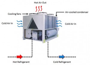
Figure 1: Air cooled chiller
Factors affecting performance of the chiller :
- One of the important factor is the condition of intake air to the chiller. If the intake air is of good condition (with minimum possible temperature), chiller operates at good efficiency.
- The condition of intake air depends on many factors including wind conditions, location of chiller with respect to wall and other surrounding equipments.
- The correct location of chiller is the one where inlet of chiller always receive fresh air from surrounding without much of resistance from surrounding obstacles.
In order to determine the effect of chiller behavior at the installed location, a CFD analysis of the outdoor environment around the chiller is carried out. The CFD analysis is done to give insight into effect of chiller exhaust and ambient air conditions on the velocity and temperature pattern within the outdoor environment of chillers. The wind conditions are different throughout the year. The wind conditions for different months are considered during the analysis. For this study, the average value of wind conditions for each month is considered. The analysis is done for 12 different wind conditions representing 12 months wind speed, direction, and temperature.
CFD Methodology :
a. CFD Domain :
In order to capture the wind flow behavior, large amount of atmosphere is also considered in the analysis. The extent of atmosphere is selected based on criteria of “unaffected flow on the boundary of atmosphere domain due to presence of other components on the roof of the building”.
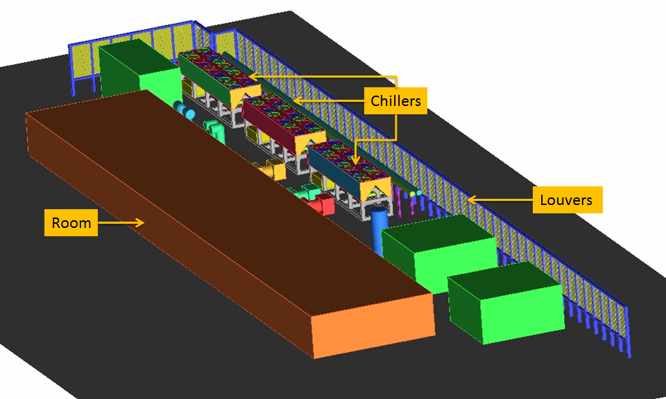
Figure 2: CFD domain with component details on the roof of building
b. Grid Generation :
CFD is the numerical method of solving governing equations related to fluid flow and heat transfer. In order to get the numerical solution, the CFD domain also needs to be divided into small sub-domains or cells. The process of generating such cells is called as grid generation process. Grid generation is the 2nd step in complete CFD cycle. As the domain size is complicated unstructured grid generation method is used.
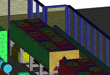
Figure 3: Mesh detail
c. Solution :
In order to get pressure, velocity and temperature distribution at various points within CFD domain, continuity and X,Y,Z momentum and energy equations are solved using finite volume method. Steady-state, incompressible flow equations are solved. To capture the turbulent behavior of flow, turbulent flow equations are solved using RANS based turbulence model.
d. Results :
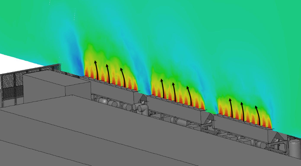
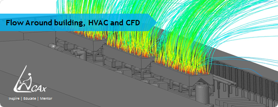
Figure 4: Flow coming out from the chillers exit
e. Conclusion :
Based on path lines, velocity, and temperature contour plots, it is concluded that there is no recirculation of hot air coming out of chiller back to the chiller inlets throughout the year. All the chillers are always getting the fresh air at the inlet. So it is concluded that the location of chiller with respect to other components on the roof of the building is appropriate.
CFD has played a crucial role in decision making. With the help of CFD we were able to conclude that the location of chillers is appropriate ensuring it does not hamper the performance of the chillers.