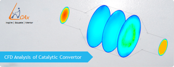
CFD Simulation of Flow in a Catalytic Converter
As the performance of a catalytic converter is substantially affected by the flow distribution inside the substrate, a uniform flow distribution can increase its efficiency, lower the pressure drop and optimize engine performance. The flow distribution in a catalytic converter assembly is governed by the geometry configurations of inlet and outlet cone section, the substrate and exhaust gas compositions and therefore a better design of the catalytic converter is very important. In this blog we shall have insights of CFD modeling approach of flow inside a catalytic converter with the help a flow visualization.
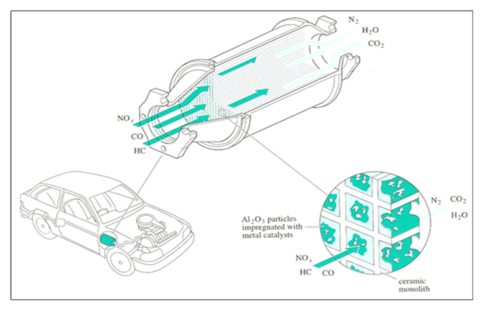
In recent years, as the automotive industry is growing, one of the major expectations from future vehicles is to meet emissions regulations (e.g. for European market, Euro IV emissions regulations effective from 2006 should be met). Therefore, the usage of catalytic converters in exhaust systems seems promising feature. Basically a catalytic converter is a device used to reduce the emissions from an internal combustion engine. Pollutants like carbon monoxide, oxides of nitrogen, hydrocarbons and volatile organic compounds (VOC) are transformed into nitrogen, carbon dioxide and water vapor by chemical reactions in the catalytic converter.
 (Source: http://catalyticconverters.com/)
Catalytic converter types from application perspective :
There are two major catalytic converter applications used in automotive industry:
Diesel Oxidation Catalyst (DOC) used in diesel engine applications and Three-way Catalytic Converter (TWC) used in gasoline engine applications.
1. Diesel Oxidation Catalyst (DOC):
These are mainly used to remove carbon monoxide and hydrocarbon in diesel engine applications. The emission conversion efficiency of DOC increases with exhaust gas temperature.
2. Three-way Catalytic Converter (TWC):
These are mainly used for NOx emission control which can’t be provided by DOC. In TWC, the above mentioned chemical reactions can effectively occur only when the air-fuel ratio is around 14.7. Due to these reasons, TWCs can’t be used in diesel engines despite the NOx emission control limitations of DOCs.
Device Understanding :
The Catalytic Converter is a vehicle emission control device which converts toxic byproducts of combustion in the exhaust of an internal combustion engine to less toxic substances by way of catalyzed chemical reactions. In catalytic converters, the design of inlet cone is of utmost importance, since it determines the gas flow distribution over the substrate (a structure located inside the converter where the emission conversion reaction takes place.) The substrate includes the active catalyst material such as Palladium, Rhodium and Platinum which initiates chemical reactions to convert exhaust pollutants into less harmful materials. This substrate may be either metallic or ceramic substrate and is modeled as porous media in CFD.
Objective of CFD Study :
The main objective of CFD study is to simulate fluid flow and heat transfer in a Catalytic Converter in order to determine:
- Internal flow pattern inside the converter and its impact on flow distribution
- To determine the flow distribution over inlet of substrate
- To determine velocity and pressure distribution across the Catalytic Converter
In case, if the flow distribution on substrate inlet is not even, then design modifications in geometry would be made.
CFD Analysis and Results :
Computational Fluid Dynamics (CFD) has been used to determine the flow patterns and pressure drop across the Catalytic Converter. Catalytic Converter consist of substrate, where emission conversion reaction takes place.
- High quality mesh is needed to capture all the geometrical features (substrate) of the 3D CAD model and to get good end results.
- Air as a working fluid is modeled here. Turbulent flow equations are solved for fluid flowing through converter.
- The substrate is modeled here as a porous medium. Porosity in terms of viscous and inertial resistance properties is defined.
- After a number of iterations it is seen that for the given inlet velocity of 22.6 m/s, the flow distribution at substrate inlet is uniform.
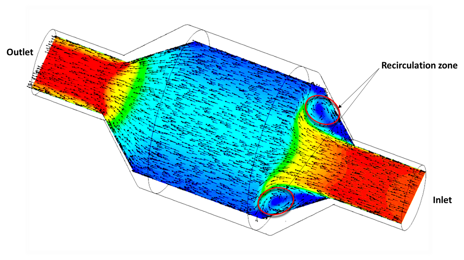
Velocity contours on mid plane passing through Catalytic Converter
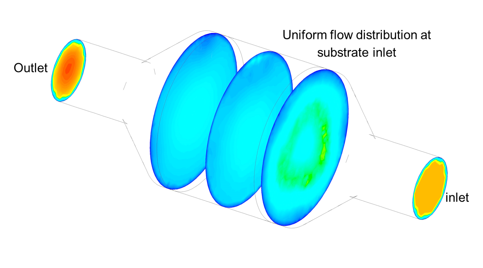
Velocity contours at various cross sections in Catalytic Converter
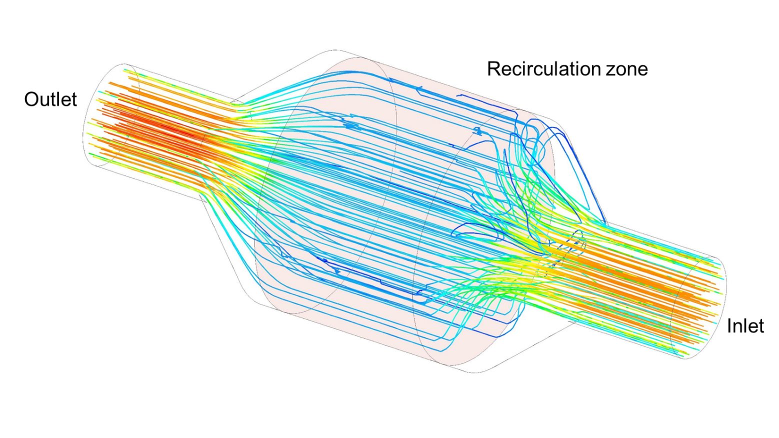
Velocity path-lines passing through Catalytic Converter
Porous Media :
Porous media can be used for modeling a wide variety of engineering applications, including flows through packed beds, filters, perforated plates, flow distributors, and tube banks. It is generally desirable to determine the pressure drop across the porous medium and to predict the flow field in order to optimize a given design.
Characteristics of the porous medium are generally defined in solver in terms of following properties:
- Porosity
- Viscous resistance
- Inertial resistance
If we have experimental Total Pressure Drop vs. Mass Flow Rate data, then we can easily get the viscous and inertial resistances for that porous media. The viscous and inertial resistances to flow in a porous medium can also be calculated from the Ergun equation, which gives the total pressure drop through a porous medium.
Here, Total pressure drop = Viscous loss + Inertial loss
Output :
- The performance calculated for this design was verified using CFD.
- The flow distribution over substrate inlet is uniform.
- The pressure drop across the device is within the permissible range. Hence, further design modifications in the geometry is not needed.
Conclusions :
- The flow uniformity over substrate inlet is analyzed and found uniform using CFD method.
- For the current design configuration, exhaust gas conversion efficiency was found to be optimum.
- Optimum pressure drop across catalytic converter indicates reduced work load of converter.
Below can be seen a beautiful flow visualization animation video of flow inside a catalytic converter:
|
{modal index.php/en/?option=com_content&view=article&id=127}
 {/modal} {/modal}
{modal index.php/en/?option=com_content&view=article&id=127}
 {/modal} {/modal} |
References :
- http://www.catalytic.co.uk/
- http://www.walkerexhaust.com/support/understanding-catalytic-converter/evolution-of-the-catalytic-converter
- http://www.cd-adapco.com/sites/default/files/Presentation/COVENTRY_0.pdf
The Author
{module [317]}