Basics of Grid Generation for CFD Analysis
Grid generation or meshing is a very critical part within the CFD simulation process as it not only dictates the simulation time but also the accuracy of results of the study. Generating a very coarse and poor quality mesh/ grid often leads to non-physical or highly inaccurate simulation results though may be solved on a very powerful solver. Hence the grid generation skills, capability and its exposure are of equal importance as much as that of the solver operations.
Grid generation is a challenging operation during which the engineer has to maintain accurate mesh density as well as ensure that the mesh count is not impractically high. To achieve these skills there are various aspects a fresher CFD engineer has to understand and get familiar with, that blog intends discuss.
Why Grid Generation Step in CFD Process ?
Computational fluid dynamics is a method of solving governing equations using numerical methods like finite difference, finite element or finite volume. The governing equations (that are either in differential form or integral form) are discretized and rewritten either at a point, an element or at a control volume (also called as cell). As the equations are written and solved in discretized form the domain or the geometry in which these equations will be solved also needs to be discretized. So as to facilitate this the solution of governing equation using numerical methods we need to give following inputs to the solver:
- Shape and size of the domain: this defines the region in which the equations are solved
- Discretize the domain: as it will be given to the solver solving governing equations in discretized form
- Identify the domain boundaries: as during solver set up we need to give appropriate boundary tagging (also called as setting up boundary conditions)
- Writing mesh: as with all this information is then needs to be written in the file or format understood by a selected solver.
The uniqueness of boundary conditions is decided by the shape, size as well as value of known flow property on the boundary. Also if the physics of the problem is same then in CFD analysis same governing equations are solved.
To explain this lets take an example i.e. imagine that you want to find out pressure drop across inlet and outlet of a duct and a control valve, in both the cases you need to solve an incompressible flow of a water. In this case a continuity equation, three momentum equations (along x, y, z directions) and turbulence equations are required. But if you look at the end results you can easily notice that the flow feature is different in a duct and that of a control valve. This difference is the result of difference boundary conditions used for both the cases, and hence to result into a unique solution of governing equations we need to give unique boundary conditions.
Pre-processing in CFD Process:
A typical CFD preprocessing activity involves creating the shape and size of the domain, this is generally supplied through:
- CAD data: This CAD model generally created using a CAD software or geometry modelling tools available in commercial software like ANSYS ICEM CFD. In ANSYS ICEM CFD due to the limited modelling features available it is usually used to create simple geometries. In case of complex geometries a standard CAD software is used which can create a complicated CAD model in short period of time. But this comes with its own limitations that may require CAD repair.
- The next step is dividing the domain in small parts or small sub domain. This process is also called as mesh generation, grid generation or discretization. There are various methods of grid generation, broadly divided into three main categories namely Structured multiblock meshing, Cartesian meshing and Unstructured meshing method.
- Once the typical grid is generated the next step is defining boundary tags and domain tags. The boundary tags involves labelling the surfaces of the domain with labels like inlet, outlet or a wall. The domain tags involves labelling the volume with solid or fluid.
All these information is then exported in a correct file format understood by a CFD solver. Thus to summarize, the overall preprocessing activity involves geometry modelling, grid generation, boundary tagging and grid export.
Grid generation steps:
Further, let us look at the fundamental definition of a grid or a mesh. The simplest definition of mesh or grid is "the process of dividing the domain in small sub domains". We can imagine the smallest sub domain as equivalent to a control volume used in the derivations of fluid dynamics and heat transfer equations. The small sub domains are referred as cells or elements in CFD community. As discussed before the requirement of mesh generation is mainly due to the method of solving governing equations, used numerical methods like FDM, FEM or FVM to solve the discretized form of the equations. This also demands for discretizing the domain or creating the grid. For any CFD engineer or to be specific for any preprocessing engineer the grid generation task is divided into two following sub activities:
- The first step involves dividing the surfaces or boundaries of the domain into 2D elements like triangles or quadrilaterals.
- The next step is dividing the volume into shapes like tetrahedral, hexahedral or prisms.
It is not necessary to use only one type of cell for meshing entire control volume, as in many cases a mesh can include combination of all type of elements. To elaborate more on the definition of grid refer to the figure below, in this case the domain of our interest is in which we want to solve the governing equations is the region between the two concentric circles.
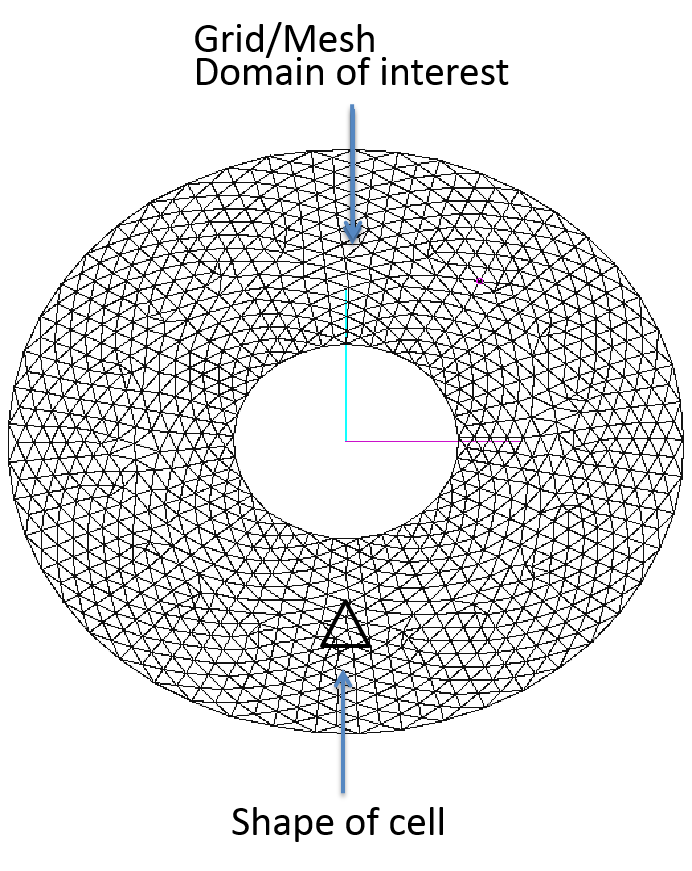
For creating the grid we have selected the simple triangular shape for sub domain or a cell. After completion of grid generation process the domain is filled with set of triangles. The generated grid should follow some governing law and some critical properties.
- The first important property is that all the triangles should collectively fill the complete domain and there should not be any unmeshed region in the domain of interest.
- The second property is that none of the triangle should intersect with each other.
- All the triangles should be connected to its neighbors at their vertices.
If you closely observe the grid generated between the region of two concentric circles it follows all the critical properties.
Quality of a Grid:
Apart from these to get good quality solution we should also look at other properties of a mesh, this includes:
- quality of a mesh,
- distribution of mesh nodes and its growth ratio
- and others.
We may later look at the different quality criteria one should check before submitting it to the solver. There are many governing factors which decides the shape of the cell one should select for meshing. The most important factor is that the selected shape should be supported by the solver.
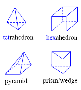
During the solution of governing equation solver needs to do some mathematical calculations over every cell, this includes calculation of properties like volume of first cell, surface area of a cell face as well as face normal. This is possible only when solver implementation has specific functions for such mathematical calculations. So before selecting any cell type one should always check the type of cells supported by intended CFD solver. ANSYS FLUENT has support for wide variety of shapes. It supports triangles or quadrilateral elements in 2D, many times these are referred as tri and quad elements. In 3D it has support for tetrahedral, hexahedra, pyramid and prism elements. In general tetrahedral and hexahedral elements are referred as tet and hex elements. A typical meshing activity involves generation of all type of elements, ANSYS FLUENT supports non-conformal interfaces between two meshed regions. The 2D an 3D elements are shown below:
2D Elements :
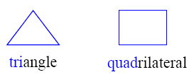
3D Elements :
Grid generation methods :
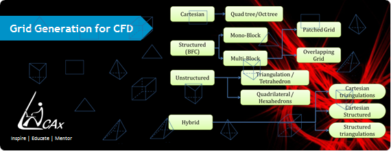
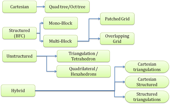
There are many grid generation methods and advancement in various algorithms has enabled creation of high quality grid within small amount of time. All the methods are broadly divided into three categories namely;
- cartesian grid generation methods,
- structured grid generation methods
- unstructured grid generation methods
- hybrid grid generation methods
To know more about these can refer to the earlier blog: Grid Generation for CFD Simulation : Introduction. The structured method is further divided into mono block and multi block method. There are large amount of unstructured grid generation algorithms, the most popular ones includes octree based methods, advancing front methods and Delaunay triangulation method. Generally unstructured mesh results into tri surface mesh and tet volume mesh. There are also unstructured methods which can generate quad as well as hex elements. Hybrid mesh generation involves using more than one meshing methods for generating mesh for entire geometry. Typically a simple region is meshed using a hex element using a multiblock approach and a complicated region is meshed with tet elements using unstructured approach. The two region are either merged with a layer of pyramids or combined with a non-conformal interfaces. The classification of different kinds of grids are as shown below:
The Author
{module [317]}