Tutorial: CFD Simulation of Unsteady Flow Past Square Cylinder
The main objective of this tutorial is to provide step by step guide to perform CFD analysis of unsteady flow using ANSYS FLUENT software. To conceptualize the idea of unsteady flow over a structure, in this tutorial we have considered flow of water over a square cylinder. One of the objective is to learn the process of solving unsteady flow past square cylinder, but the important objective is to understand vortex shedding created on an object. Once the technique is learned, you can apply same procedure for practical cases like flow over tall chimney, building structure, overhead power lines.
| ANSYS FLUENT |
| Beginner |
| No Specific Industry. Academic Validation Problem |
| Academic Problem Series |
| Trushna Dhote & Praveen Kumar |
| CFD, ANSYS FLUENT, Unsteady Flow, Vorticity, Von Karman Vortex Street, Lift, Drag |
| Course : CFD Simulation with ANSYS FLUENT |
This tutorial is part of our FREE course "CFD Simulation with ANSYS FLUENT". Visit the course page to see the details of the course and subscribe the course.
Instruction to Download PDF Instruction, Input and Solution Files
A PDF copy of this tutorial guide is provided for download. This tutorial guide includes step by step instructions to repeat and try this tutorial on your own. A necessary input mesh file is available for download. ANSYS FLUENT solution files (case and data file) and animation file is also available for download and check the simulation setup details and verify your results.
All these files are available in the download section of this tutorial. You need LearnCAx account to download all the files. If you do not have an account, create your FREE LearnCAx account here. Just login with your LearnCAx account and you will see all these files in the download section provided at top.
Introduction
When a fluid flows past a structure at a certain velocity, vortices known as Von Karman Vortex Street are created downstream of the body and detach periodically from either side of the body. Due to the alternating low pressure zone from either side of the structure, vibrations are induced in the structure. If the frequency of this vibration coincides with the natural frequency of the structure, it may lead to damage/failure of the structure. One of the classical case of structure failure is Tacoma Narrows Bridge (http://en.wikipedia.org/wiki/Tacoma_Narrows_Bridge_(1940)(1940). This classical case is well recorded. You can watch the YouTube Video and see how the small forces generated due to unsteady flow feature causes huge structure to collapse.
Vibrations induced due to vorticity occurs in many engineering structures such as bridges, transmission lines, offshore structures, thermos wells, engines, heat exchangers, marine cables, towed cables, etc. At very low Reynolds number, the streamlines of the resulting flow is perfectly symmetric. However as the Reynolds number is increased, the flow becomes asymmetric and leads to vortex shedding.
This tutorial explains the CFD analysis of vortex shedding using ANSYS FLUENT software. A mesh file is provided as input for this tutorial (This tutorial will not cover mesh generation steps). The tutorial will cover simulation and post processing steps.
Objective of Tutorial
The main objective of this tutorial is to provide step by step guide to perform CFD analysis of unsteady flow using ANSYS FLUENT software. To conceptualize the idea of unsteady flow over a structure, we have considered flow of water over a square cylinder. Once we understand the procedure to capture physics around square cylinder, we can further replace the square cylinder by any structure like building, overhead cables, etc. All the steps right from providing inputs for flow simulation to post-processing and result interpretation are covered in this tutorial.
Prerequisite
Following are the prerequisites for using this tutorial:
- You should have basic understanding of fluid mechanics
- You should be familiar with ANSYS FLUENT software interface
- You should have access to ANSYS FLUENT software
- We tried to provide detailed explanation about each step. Some of the steps might not include very minor details about doing setup in ANSYS FLUENT. It is assumed that you are familiar with ANSYS FLUENT and solved coupled of simple CFD problems
- It is recommended that you have a computer system with 2 GB to 4 GB RAM in order to setup and run this tutorial simulation
- You should have access to PDF file reader to read this PDF file
Benefits of Tutorial
After this tutorial, you should be:
- Able to solve unsteady flow problems using ANSYS FLUENT
- Use K-ε Realizable model (Turbulent Model) to analyse this problem
- Set-up the case with appropriate material, boundary conditions and solver settings
- Set-up solution animation for unsteady problem
- Understanding the steps for auto saving the case and data files
- Calculating time step for simulation from Strouhal number
- Post process the results to display and analyse vortex shedding
- Calculating Strouhal number for simulation
Vortex Shedding and Its Importance
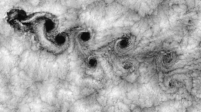
Figure : Von Karman Vortex Street
Image source: http://en.wikipedia.org
Vortex shedding is a complex physical phenomenon in which a fluid such as air or water hits a bluff (as opposed to streamlined) body at certain velocities, vortices, known as Von Kármán vortex street, is created downstream of the body and detach periodically from either side of the body. The fluid flow over the object creates alternating low-pressure vortices on downstream side of the object. As the fluid flows to fill the low pressure zone, it produces a vibration at a specific frequency. If these vibration coincides with the natural frequency of the bluff body, it may lead to damage/fatigue failure of the body. The frequency of the vortices depends on the shape of the blunt body, and the velocity of the fluid flow or wind hitting this body.
For example, if the frequency of vortex shedding matches with the resonance frequency of the tall structures like buildings, it may lead to damage/destruction of structure. Failure of Tacoma Narrows Bridge in 1940 proves a good example of significance of CFD analysis of flow over a bluff body to avoid such failures. (To know more visit: http://en.wikipedia.org/wiki/Vortex_shedding )
CFD Problem Description
To perform and understand the simulation of unsteady flow over a bluff body, we have considered water flowing over a square cylinder. (In practical application, bluff body/square cylinder could be a tall chimney, building structure, overhead power lines, etc.). The flow is considered to be unsteady at velocity of 0.535 m/s and square cylinder size is 0.04 m. Density of water is assumed to be 1000 kg/m3 and viscosity as 0.001 kg/ms. The geometry is reduced to 2D for ease in simulation.
In this problem, the flow separation occurs at upstream sharp corners due to the abrupt change in geometry. Due to this, the flow diverges and creates a wide wake downstream of the flow. Larger wake gives rise to higher drag and smaller value of vortex shedding frequency. In flow over a square cylinder confined in a channel or subjected to a free-stream flow, various complex phenomena like flow separation, reattachment, recirculation, and vortex shedding occurs. Hence it provides a very challenging flow field for both experimentalist and CFD practitioners. Therefore, the simulation of unsteady flow past square cylinder has been considered.
Geometry consists of square cylinder with characteristic dimension of 0.04 m. The computational domain extends to 8.5 times the square cylinder in Y direction and 10 times upstream and 30 times downstream of square cylinder. (You may change the extent of computational domain as per our experience. There is no any stringent criteria but one has to ensure that there no pressure gradient or velocity gradient across the top and bottom boundaries)
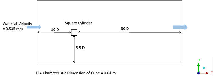
Figure : CFD Flow Domain
CFD Solution Snippets
These are the few snippets of CFD simulation results from this tutorial
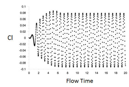
Figure : Lift Coefficient vs. Flow Time
From above figure, it becomes clear that the flow is oscillatory in nature. Cl value oscillates in between + 0.09 and -0.09. We can calculate the Strouhal number from result of Cl vs. flow time. The cl-history file created during solution is an ASCI file containing data of Cl vs. flow time. For better visualization and data extraction, open this cl-history file in Microsoft Excel (or equivalent plotting tool). Create the plot of Cl vs. Flow time. Take an average of 10 shedding cycles (We have used cycle pick values) as shown in below figure.
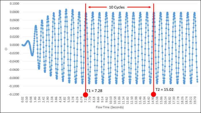
Figure : 10 Cycle Average for Strouhal Number
Now, calculate the Strouhal number as:
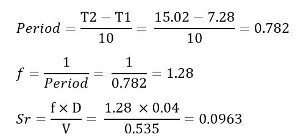
So the calculated Strouhal number for this analysis is 0.0963
Vortex Shedding Animation
Tutorial Contributor(s)
{module [327]}
{module [326]}